|
17 - Electrical and Instruments ( Chris Burdo,
June 7, 2005
)
17.1 - Positive to Negative Polarity Swap ( Frank Benschop,
)
The following are instructions on changing to negative ground for a positive ground saloon:
* Turn the battery around, or preferably, find one with the poles reversed (limits the possibility of shorting on the back of the open bonnet).
* Reverse the wires on the ignition coil.
* Inspect your fuel pump for a capacitor (common on later Mk 2/240/340/S-Type). If there is no capacitor, go on to the next step. The capacitor in the fuel pump is a one lead axial type. The lead is the negative pole. The positive pole is the housing, which is earthed by the attachment clip. There is no simple way to 'reverse' it. Replace the capacitor with a 50uF electrolytic capacitor of at least 20Volts with about the same physical dimensions. Solder the positive pole to where the old lead was attached. Solder the negative pole to the attachment clip or other suitable earth.
* Run a wire from the positive post of the battery and briefly "zap" the field terminal of the generator (reverses the residual field).
* Reverse the wires on the ammeter (hard to get to on a Mk 1).
* For Mk 2 and later cars, the clock in the rev counter should be disconnected. Otherwise it gets fried. No easy way to convert it. This will probably not be a problem in most cases as the clock in most cars is already broken.
* If the car has an original radio, you will need to either disconnect it, or electrically isolate it from the rest of the chassis (including the antenna) - Mark Stephenson.
* Start it up and go for a drive.
There is no need to fiddle with the wires to the starter, fan motors, etc. They seem to sort things out on their own. There is some indication that the washer bottle mechanism in the Mk 2 and later Saloons is polarity sensitive.
17.2 - Clock Removal from Tach ( 3.8S,
February 5, 2005
)
Get a small ratchet with a 3'' extension and a 1/4'' socket.
The 3'' extension is needed because the head of the ratchet
will not allow you to get the socket in place.
Set the ratchet in the ''remove'' position. There are two 1/4'' nuts
and washers at the bottom of the tachometer, one on each side of
the clock. A small mirror and a flashlight will help you see them.
You must remove the two nuts. You need to remove the knurled
brass ''nut'' of the setting cable from the back of the clock, and
disconnect the one wire from its connector. Then carefully pull the
clock until it dislodges from inside the tach. It will come out but
gently, no force is needed. When it finally comes out, there is
also a rubber gasket which might fall out.
To reinstall it, get a Glue Stick at any school supply, and glue the
gasket to the clock assembly so it remains in place while re-mounting
the clock. This glue is inoffensive and will keep the gasket in place
just enough so that it will not move while re-mounting.
17.2.1 - Eck Clock Conversion ( Mike Eck,
February 26, 2005
)
I do NOT remove any parts from the clocks. I use all of the original
mechanism that is in the clock. I ultrasonically clean the clock, then
lubricate the bearing points with clock oil. I carefully clean and adjust
the contacts, and coat them with a thin film of Deoxit D100L contact
cleaner and rejuvenator. Then I install a circuit board which works
with the original mechanism to reduce the contact current and provide
a consistent power pulse to the coil. It still ticks and the time set stem
works as it should. None of the original clock parts are removed, so
the installation is totally reversible, in case you ever want a non-functional
clock again!
The Smiths clocks are actually very well made, with jeweled bearings and
brass gears. There are no metal tabs. The clocks are assembled entirely
with screws, so individual parts such as the balance wheel, electrical
contacts and gears are replaceable. Since the weak point in these clocks is
the electrical contact, the clocks never seem to run long enough for
anything else to wear out. I have upgraded about 150 of these clocks, and I
have never yet seen one that I couldn't fix.
Thanks for the opportunity to clarify this point. If you need any more
information please see my website, www.jaguarclock.com, or contact me off list.
Mike Eck
New Jersey, USA
www.jaguarclock.com
17.2.2 - 420G Clock Battery ( Larry Martz,
August 14, 2002
)
Nigel Thorley's JAGUAR MARK VII TO 420G - THE COMPLETE COMPANION discusses
the 420G battery clock on p/134: "In October (1969), the mercury-cell-powered
electric dashboard clock was replaced by one powered by the electrical
system of the car itself. The new clock was part no. C.32437 (old
mercury-cell-powered, C.26989) and this became effective at chassis nos.
GID.57384 RHD and GID.77983 LHD. Due to lack of availibility of the
earlier battery-powered clocks, dealers were requested to amend the wiring
of existing cars to suit the new clock."
NOW, I amplify this somewhat -- Nigel Thorley made NO mention of the
electric clocks in the Mark X, because these were NOT battery-powered, eh!
In fact, for 420G owners, check your chassis #s to determine if your 420G
was built before GID.57384 RHD and GID.77983 LHD -- after October 1969 at
these chassis #s, the 420G reverted to the standard clock, powered by the
Cat's electrical system, with NO battery. I hope this helps
17.3 - Upgrading the Stereo for a S-type ( Dave Symington,
August 10, 2005
)
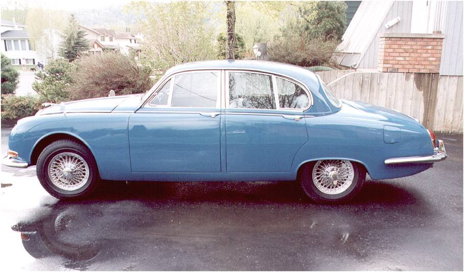
Dave and Diane Symingtons 1966 S-type
ST-06
ST-07
ST-18
ST-2

ST-19

ST-12
ST-11
ST-13
ST-16
ST-09
ST-10

ST-14
ST-08
ST-17

ST-21
|
New Stereo System in 1966 S Type
Ever since the major part of the restoration was completed on our S-Type Diane and I both knew that
we had to get something done about the radio! The existing ôsystemö was a Blaupunkt AM/FM/SW
radio with only one speaker mounted behind the grille on the drivers side of the centre console.
It had very bad sound!
What we wanted was a good AM/FM receiver, capability to play CDĺs and good quality sound with front and rear speakers. One of the main concerns was that whatever system we installed, it had to look like it belonged in the car. Some of the newer receiver units wouldnĺt look out of place on the space shuttle and that was not what we wanted. We donĺt put our car in shows but we both felt that we had to maintain the original look of the radio. We had converted our car to 12volt NEGATIVE ground earlier so there was no problem with this installation.
We eventually decided to have the radio insides replaced with a modern digital AM/FM while still retaining
the original body and face of the Blaupunkt radio. We wanted a CD changer mounted in the trunk out of
sight. Good front and rear speakers to complement the system was also in order and sufficient power
from the radio so that no additional stereo amplifier would be used if possible. Through the Jag Lovers
resource pages we found Antique Automobile Radio Inc in Palm Harbour Florida,
(www.antiqueautomobileradio.com). We talked with Matt and decided to have him do the conversion of
our radio. They also provided a 10 disk Prestige CD Changer that would work with the new radio. The
speakers we purchased through (www.discountcarstereoplus.com). Specifications for the components
are as follows:
AM/FM receiver:
12 volt negative ground
Digital signal processor.
Original Blaupunkt body and faceplate
Push buttons work for both AM and FM
Tuner knob functions as before
Front to rear fader
Balance control
Treble/bass control
Manual tuning also
4 BTL amplifiers 45watts RMS each built in.
Control wire for switching the power antennae
CD Changer
Audiovox/Prestige 10 CD changer Model SP-11CDP
Hard wired to AM/FM radio
5 - 20,000Hz
Signal to noise 85db
Channel separation 80db
Hard wired controller
Remote wireless controller.
Speakers
Front
Infinity Kappa series 42.5i
4 inch 2way with crossover
50w RMS, 150w peak
sensitivity 90 db
Frequency Response: 75Hz - 21kHz
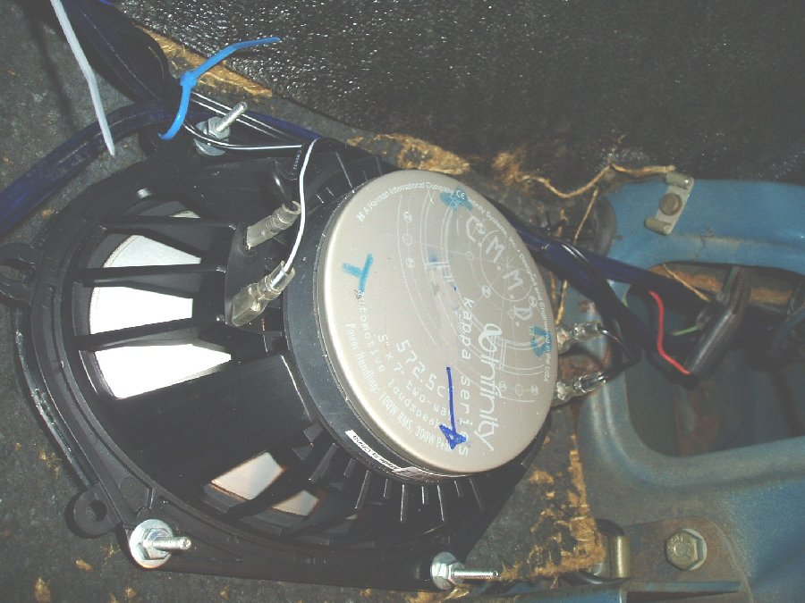
Rear:
Infinity Kappa series 572.5cf
5 inch by 7 inch 2 way with crossover
100w RMS, 300w peak
Sensitivity 90db
Frequency response 40Hz - 21kHz
Mounting the components:
Before doing anything disconnect the battery!
(Photo ST-01)
Radio:
Pry off the heater control buttons and youĺll see the two mounting screws for the wooden radio faceplate.
Remove these screws and remove radio. Disconnect wires and antennae wire.
The centre console of the Jaguar needs to be removed so this means you need to take out the front seats.
The vacuum lines for control for the heater need to be removed (Best to tag these so they go back
on the correct way)
The hand controls for the heater vents over your feet need to be removed.
The leather covered bump pads on front of parcel shelf will have to be removed.
The heater outlet hose for the rear heat will need removal.
Once the console is removed, remove the original speaker from left side.
The body or frame of the radio did not change so everything will fit back in as it was. There is now a little
extra room in there as the separate 12volt power supply box needed by the Blaupunkt is not required now.
The case of the radio is modified to allow the RCA plugs from the CD device to be attached. We asked
this to be done at the rear of the radio but in retrospect there is actually more space on either side of the
radio chassis so if I were to do this again, this is how I would have asked them to do it.
The power wire was attached to the original wire which is fused with a 14 amp fuse. And is switched with
the ignition.
There is an orange wire for control of the power antennae
There is also a power wire for switching the CD changer on.
There are the eight wires for the four speakers.
All wiring for the radio goes through a multi pin connector making it easy to remove the radio in future
without cutting wires (See problems)
One thing you need to do that is NOT in the instructions is install a good ground wire between the radio
chassis and the SAME ground that is used for the CD player controller. (See problems)
As they say in most of the other stuff Iĺve read. . . . Install in reverse order of removal!
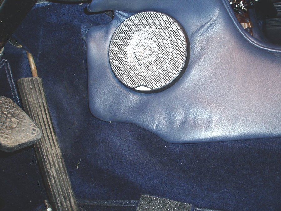
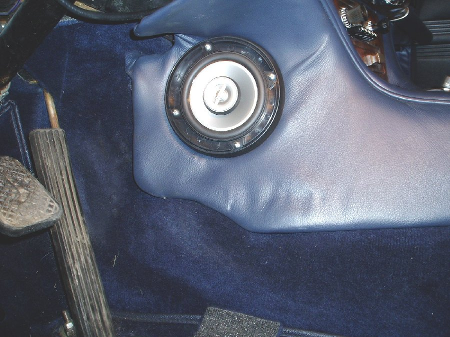
Front Speakers:
(Photo ST - 06 and ST -07)
The Infinity Kappa speakers chosen will exactly fit the screw holes from the original speaker grille on the
car. At least on my car they did! I discarded the original speaker grilles as the Infinity speakers came with
grilles that fit perfectly. The installed height of the Kappa speakers are just under 2 inches which is less
than the original so there is a good fit here! Just be careful where you mount the cross-over devices.
There is a good wiring diagram supplied by the speaker manufacturer and the wiring connectors are
different sizes so as not to get positive and negative confused.
As there was no original speaker on the right side youĺll have to make some modifications.
First, the leather behind the right speaker grille will have to be cut and glued back over the console
support material. Cut leather in a star shaped pattern and use some spray headliner or upholstery
adhesive to hold it in place.
Second, the heater control mechanism for switching on and off the rear heat is mounted in the way of
where youĺll mount the right speaker. This control will have to be removed and a longer piece of 2 inch
heater ducting installed. You may be able to fabricate a device to allow keeping the heater control. I
decided to remove it.
Mount the speakers and the in-line crossover on each side of the console. I used machine screws through
the new grille bases and nuts on inside.
Put a little Locktite on the screws to stop the nuts vibrating off and screw everything together.
The new speaker grilles are pushed into the grille bases after the console is installed.
The speaker wires can be connected to the wires and plug supplied with the radio. You need to observe
the correct polarity of each wire and it may be a good idea to make tags depicting location and install
them on each wire.
Note: I will probably install Bass blocker devices on the front speakers in the future as the speakers cant
handle too much Bass and may be damaged if you crank up the volume :-)
Rear Speakers:
The rear parcel shelf has three cut-outs. One large one 14.5" x 4.75" in the centre and two 4.75" square
ones on either side. The Infinity speakers chosen will fit under the square cut-outs with no modifications
to the opening. Mounting holes for the speakers will have to be drilled from below however.
The distance between the rear of the back seat squab and the rear window is only 5.75" at the point where
the rear speakers would be positioned so it would be very hard to install a 6 x 9 speaker in there. This is
why a 5 x 7 configuration was chosen.
Remove the rear seat bottom and back.
Remove the Ambla covered rear parcel shelf material (two screws about 6 inches in from the sides of the
car)
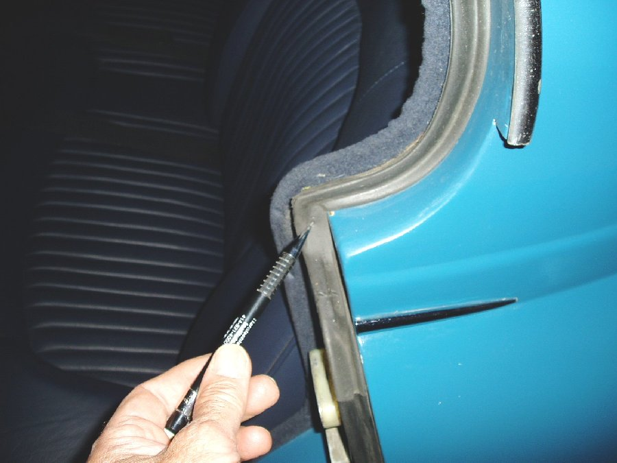
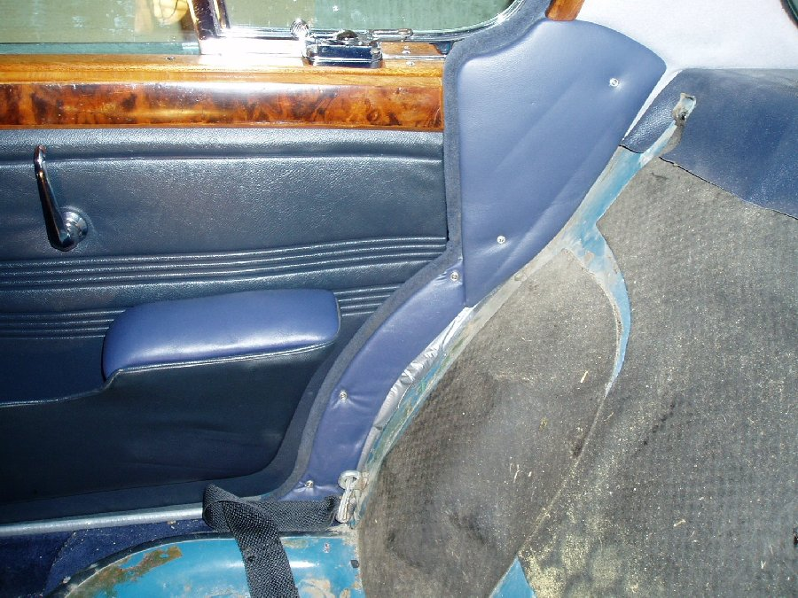
Remove the two leather covered cheek pads on either side of the rear seat squab underneath where the
rear quarterlight windows are located. There are screws coming in from the outside of the car underneath
the rubber weatherstrip material. (Photo ST - 18) Also are two screws that are visible from the inside of
the car. (Photo ST - 02)
Remove the Ambla covered crescent shaped panels underneath the leather cheek pads on each side of
the car.(Lower part of Photo ST - 02) You will be running wiring here.
I chose to mount the speakers underneath the parcel shelf as it required no metal cutting of the speaker
openings. If you choose to surface mount the speakers then you need to enlarge the speaker openings.
This would be quite hard to do from underneath and almost impossible to do from on top without
removing the rear windshield glass. I remember what a pain it was to reinstall the rear window rubber and
chrome strip and donĺt want to do that again if I can help it!
Drill speaker mounting holes and mount speakers from underneath. As there is a pronounced lip on
bottom side of the speaker cut-outs in the parcel shelf you will have to find or fabricate a spacer to go
between the speaker and the parcel shelf. This should be about 3/8" to 1/2" thick.
I rescued rear speaker grilles from a 1989 Mercury Tracer that had 5 x 7 speakers and was of the right
blue colour for our Jaguar. On top of these Ford speakers there was a gauze covered spacer that was
exactly 3/8 inch thick that when removed, fit the Kappa speakers perfectly and acted as the required
spacer between the Kappa speakers and the bottom of the parcel shelf. If you check in local auto
wreckers you might find something that will work for your car. The Kappa speakers did not come with
custom grilles but you may find a 5 x 7 speaker from a speaker manufacturer that does.
The square plugs for the speaker cut-outs in the car were removed and discarded. The large rectangular
plug was kept and adapted for mounting the CD Player.
Place the fibreboard covering for the rear parcel shelf back in place loosely and trace the opening of both
speaker cut-outs from the bottom.
Carefully cut out the holes in the fibreboard (sabre saw with fine blade). The foam interliner can be cut out
and removed using a sharp utility knife. The Ambla covering the hole can then be cut in a diagonal fashion
and the material folded and glued to the underside of the fibreboard leaving a smooth opening in the
panel for each speaker.
The speaker grilles (from the 1989 Mercury) have four mounting pins and Pal nuts that need to be
mounted on the fibreboard parcel shelf before the shelf is reinstalled on the car. Careful measuring is
required before drilling any holes. In my case there is less than 1/4" to spare on each side of the
grille.(photo ST - 19) My grilles measure exactly 5.625" x 8.0"
If you feel so inclined you can install some Dynomat sound deadening on the metal surface of the parcel
shelf. However this will make it harder to reinstall the fibreboard cover. I had purchased some Dynomat
but ended up not using it because of concerns over fitting the fibreboard cover back in place.
(Photo ST - 12)
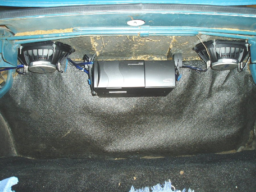
Before you reinstall the fibreboard cover you need to make the mounting arrangements for the CD player
The Kappa speakers for the rear have an adjustable tweeter in the centre of the speaker cone that the
manufacturer says should be angled towards the listener. First thought was to turn those towards the front
of the car. However we angled them backwards with the thought that the high frequencies generated
would bounce off the rear windshield and be reflected forwards. (Photo ST - 11) It seems to work
extremely well. (Iĺm slightly deaf but Iĺm sure that a dog or cat sitting in the front seat would be suitably
impressed with the high frequency rendition of the speakers!)
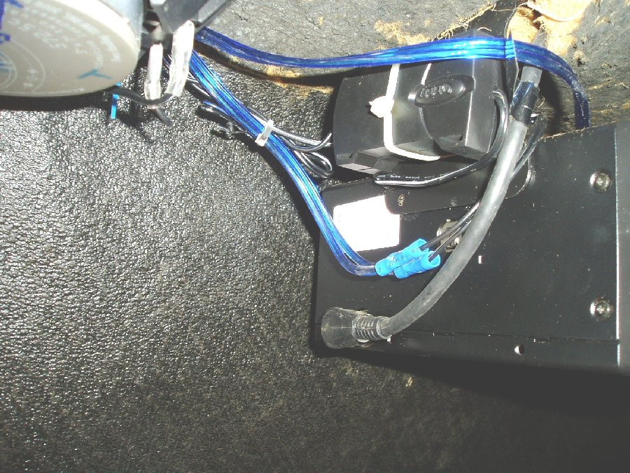
The speakers were bolted in place using the spacers as described above. The Crossovers were
attached and tied to the CD player mounts with nylon tie wraps. (Photo ST - 13)
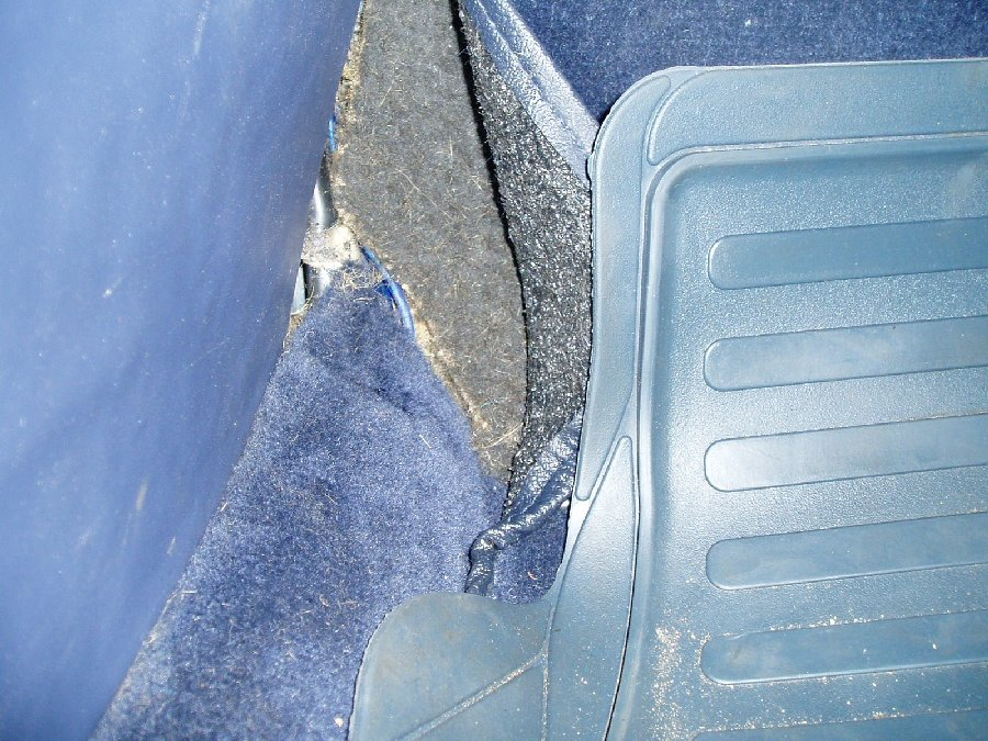
Wiring to rear of Car:
I installed the speaker wires in left side rocker cavity, DIN cable for CD player in the right side rocker
cavity. Unfortunately because of the unibody construction of the car there is no other suitable way of
stringing wires to the rear of the car. Bummer!
Jaguar had installed a speaker wire for their rear speaker option. It is probably best not to use this and
instead install new speaker wire that matches the power requirement of your speakers. We used 16
gauge paired wire ( in a nice blue colour to match the car). You are going to need about 40 feet of wire.
(I originally bought 30 feet of wire only to find I was about 2 feet too short!!)
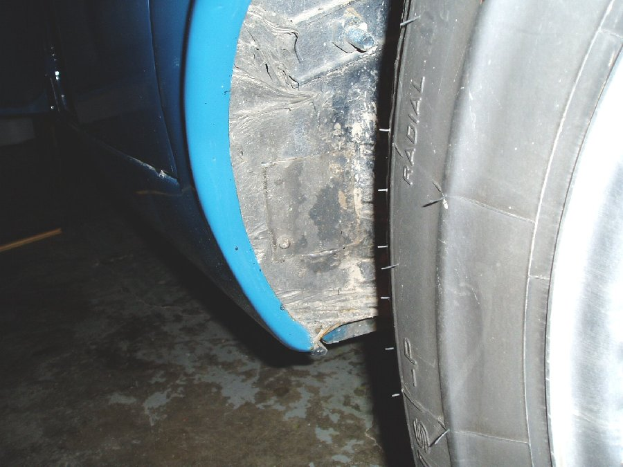
The left and right sides of the car have hollow rocker cavities that already carry some of the vehicle wiring.
These cavities can be accessed through a rubber plug in the front face of the rear wheel well. I had
replaced these plugs at time of car rebuild with a small square plate of steel screwed in place and sealed
with caulking (photo ST - 16)
Above these access plugs on the inside of the car and behind the crescent shaped coverings earlier
described is another access hole where the wiring for the rear of the car passes. (Photo ST - 02)
Wiring from both the speakers can be threaded through the grommet between the trunk and the area
behind the side Cheek Covers earlier mentioned, down and through the grommet into the rocker panel
chamber.
At the front of the car remove the Ambla covered kick panel near the dimmer switch on the left side and
the similar one on the right side. (Photo ST - 09) This will expose the wiring going through a grommet into
the rocker chamber and aft to the rear of the car. Remove this grommet. I ended up drilling a new hole
into the rocker cavity next to the existing grommet as it was very tight for the speaker wires and on the
right side of the car, it was impossible to thread the DIN cable through the existing hole.
Jack the car up or put it on a hoist and remove both rear wheels to better access the plugs in the wheel
well.
Next, you will need to find, borrow or make a ôFishing Toolö or borrow an electricians Fish Tape to thread
the wires from the rear of the car to the front through the rocker cavity. I used a fibreglass whip antennae
about 3/8" in diameter and about 10 ft long. Taped the speaker wires to the end with duct tape and
pushed the assembled mess through the hole in the wheel well up to the hole at the front of the car. I had
help from my wife here and after a few tries managed to fish the speaker wires up through the hole behind
the kick board in the front of the car.
Repeat the whole procedure to string the DIN cable for the CD player in the right rocker cavity. On this
side for sure you will have to drill a new hole for this cable on the front of the right rocker cavity as the head
of the DIN cable is too large to fit through the existing grommeted hole. Youĺll need about a 3/4" hole
With my wife helping me, and after everything was prepared, the stringing of wires on both sides of the car
took about 40 minutes. Make sure you have enough length of speaker wires at front and rear to finish
making your connections (I didnĺt!) then button everything up.
Testing the speaker wires:
Make sure that the wires are connected to the radio correctly. You can test wire continuity with a
Multi-meter, but when you make the final connection to the radio make sure that you are connecting
positive to positive etc. Then connect the wires to the plug supplied with the radio.
Mounting the CD Player.
The CD player came with an assortment of mounting brackets. I selected the ones that would allow the
player to be horizontally positioned and right below the rectangular cut-out in the rear parcel shelf (where
the optional AC unit goes)
I mounted the brackets directly to the cut-out plug with the supplied bolts and reinforced the cut-out plug
with 1/8" aluminium sheeting to make it stiffer.
The cut-out plug was then reattached to the parcel shelf and screwed in place with sheet metal screws to
hold it firmly in place.
The CD player was then attached to the mounting brackets. (Photo ST - 10)
The DIN cable on my unit plugged into the CD player on the drivers side and is the only connection
between the front of the car and the CD player.
I mounted the rear speaker crossovers to the CD mounting brackets with nylon tie wraps. (Photo ST -13)
The CD player came with screws that held the disk transport mechanism stationary during shipping.
These MUST be removed before placing the unit in service. The manufacturer also supplied sticky
decals to cover a few of the mounting holes in the player.
Install any insulating material on the underside of the parcel shelf and your done in the trunk!
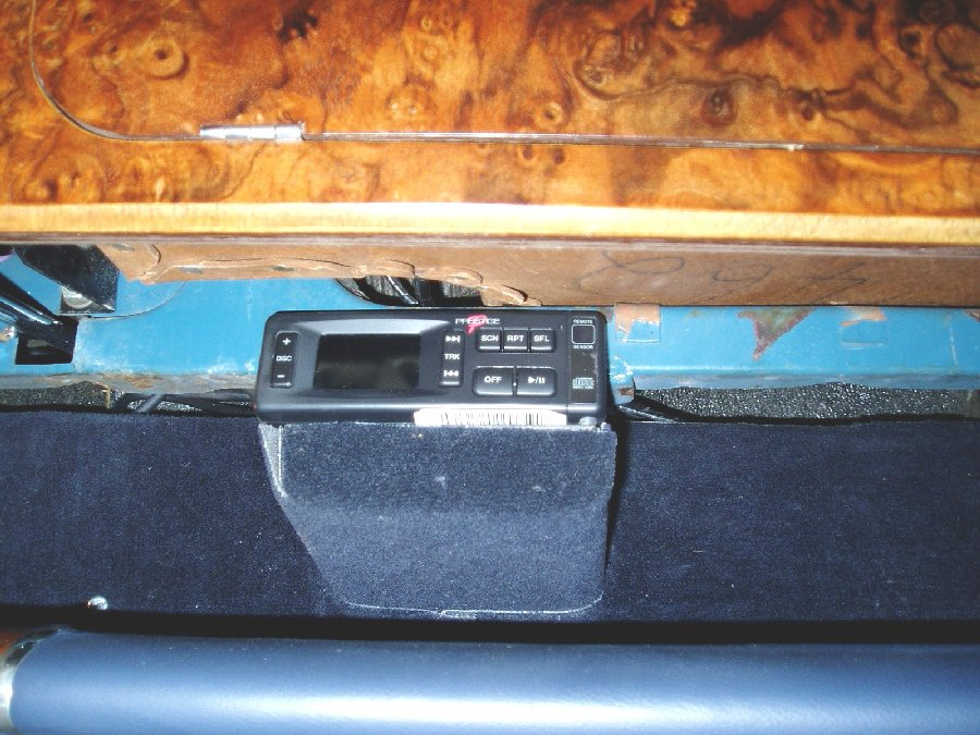
CD Changer Control box and Wired Commander Unit
At the front of the car behind the dash or front parcel shelf somewhere you need to mount the small (about
3" by 1.5") control box supplied by Antique Auto Radio that directly connects the CD to the radio. This is
NOT an FM modulator box but a powered device that takes the signals from the DIN cable and converts it
to a signal to the radio via RCA cables. The Wired Commander unit is also plugged into this box and
allows you to control the CD changer manually.
I installed the Wired Commander unit with a Velcro fastener underneath the glove box on the right side
where it is not directly visible from outside or inside the car. The Remote Control for the CD changer
needs to have a direct line-of-sight path to the Wired Commander. (Photo ST - 14 and ST - 08)
There is a control wire from the radio to the CD control box, 2 RCA cables to the radio, the DIN cable to
the CD changer and the DIN connecter to the Wired Commander to be hooked up. There is also a
ground wire. This ground wire MUST be connected to the same ground as the radio chassis. (See
problems)
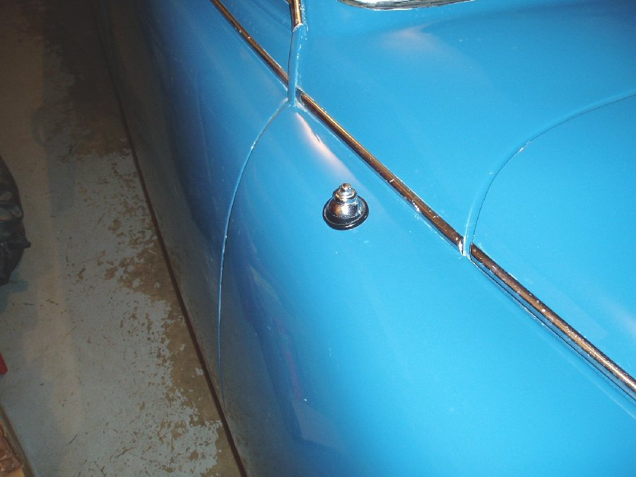
Power Antennae.
Jaguar had an option for a hand crank antennae for the radio. We installed a regular power antennae in
the same location when we rebuilt the car. It needs a fused power supply and the signal wire from the
radio. (Photo ST - 17)
Youĺre done!!
Set up the CD changer magazine with some favourite tunes or tune to a FM station, sit back and relax and
listen to your new sound system!
Problems:
1. Initially when the system was powered up it would only produce acceptable sound at very low volumes.
When the volume was turned up there was a rapid popping noise from the speakers. This was eventually
traced to be the need for the radio chassis and CD Control Box requiring a shared common ground.
This was not mentioned in the suppliers information and took quite a time for me to figure out.
2. The multi-pin connector attached to the wiring for the radio had bent pins when it arrived. It took about
30 - 40 minutes to straighten out the pins so that both sides of the plug would connect. I was tempted to
cut the plug off and crimp the wires together but that would cause problems the next time the radio was
removed.
Costs:
Radio Conversion to Digital $399.95
Shipping $29.00
CD Changer $329.95
Shipping $29.00
Infinity Kappa speakers (4) $118.98
Shipping $20.00
Customs and Import Duty $57.05
Speaker wire $20.00
Total $1,003.93 US Funds
Time taken?
You donĺt really want to know this as it always seems to take longer than what you think. Especially when
you are designing the system as you go. Once everything was figured out I expect it took me about 20
hours to do everything. Add on about an additional 40 hours for figuring out what type of system we
wanted, how to fit it into the car and finding the used speaker grilles for the rear parcel shelf (they were
free!)
Would I do it again? Yes, most definitely! It is a super sounding system that looks perfectly stock and well
worth the effort.
If anyone else is thinking about doing this I hope that this guide will shorten the time required to do the job,
(Photo ST - 21)
Best wishes,
Dave Symington symingtn@telus.net
1966 S Type 3.8 MOD (with great sound system)
|


