|
1 - Index ( ,
)
10 - Engine ( ,
)
10.10 - Electric Cooling Fan ( ,
)
Comes on at about 105 - 110║C. On UK models the radiator immediately behind the electric fan has rubber flaps which block air flow normally. These lift up when the fan blows.
10.11 - Coolant Low Sensor ( ,
)
This applies to Ĺ90 models, but not the earlier ones.
The sensor is easy to fix. Just disconnect the electrical connector, and the plastic clips that hold the wire to the side of the tank, (careful, the plastic is brittle) then twist and pull the sensor out of the tank. At the bottom of the circuit board, the trace will be eaten away by the gunk the found its way into the hole the sensor fits into. The sensor is a float inside the tank with a magnet in it and a reed switch on the circuit board that you removed. Just bridge the connection thatĺs open with a piece of wire soldered onto the points that will bypass the bad trace.
10.12 - Replacing the Thermostats ( V12 XJ40) ( Win Dooley,
)
There are two thermostats, located at the front of A and B bank. To change the thermostats, cover fenders with protective cloth. Begin by completely removing air intake boxes for A and B Bank. A 3 to 4 inch extension is required to access the thermostat housing bolts. There are three on each housing.
On B bank (US driver's side), disconnect interfering electrical connectors and air hoses, remove radiator hose at thermostat housing, remove bolts securing thermostat housing. If housing does not pop free, tap it gently. Remove old gasket, clean up thermostat housing and bolts and replace thermostat and gasket with new parts. The process is identical for A bank, but there are no interfering electric connectors or air hoses. Replace upper radiator hoses if there is any doubt as to their integrity. Change air filters if required.
The hoses can be easily reattached by lubricating them with dishwashing soap. The snorkels can be easily replaced in the fender grommets by lubricating them with dishwashing soap. Since coolant is lost by removing thermostats, it's a good time to change the coolant. Reassemble and check for leaks.
Allow 1 hour for this task.
10.13 - Waterpump replacement ( John Ping,
)
The following method is applicable to all XJ40s and 4.0 XJSs which utilize the EAC-7325 water pump or some minor derivative of that model. Expect the replacement to consume two hours of steady effort.
Typical hand tools (open end wrenches, 1/2" and 3/8" ratchets & sockets, pry bar, and large flat tip screw driver) is all that is necessary for this job. Its an excellent idea to lay several towels across the engine area (and fender) to protect components ... and to help prevent loss of small parts. A portable fluorescent (cool touch) work light is very handy.
Note: If your pump impeller assembly comes with a gasket, go ahead and install it to the impeller assembly with some silicone RTV sealant. Really helpful to have the gasket in place when attempting to install the impeller assembly ... saves a lot of effort.
1) Disconnect the negative side of the battery. Its not likely that you will suffer electrical problems during this task, but if you accidentally touch a hot connection on the rear of the alternator ... the effort to disconnect the battery will prove immensely worthwhile.
2) Using a 13 mm open end wrench and large flat tip screw driver, loosen the fan thermal clutch nuts (4) on the water pump hub. Wedge the screw driver between the hub and one of the four studs/nuts to secure the hub while loosening the nuts. Using the screw driver, lift and remove the radiator / fan shrould clips (2). In one motion, remove the radiator / fan shrould and fan/thermal clutch assembly.
Note: The shrould has no lower fasteners ... shrould tabs fit into frame slots. Store the fan thermal clutch vertically ... do not lay it horizontal so as to prevent the loss of clutch fluid.
3) If equipped, disconnect the air pump magnetic clutch electrical connector. Its a medium sized two wire black barrel connector located near the front of the intake manifold. Loosen the air pump pivot bolt. Loosen (backoff) the air pump upper jam nut and clamp bolt. The jam nuts (upper and lower) are 14 mm while the clamp bolt is 10 mm.
Note: The owner's manual has excellent diagrams of adjustment points for the air pump and alternator. Its a good idea to review these diagrams prior to starting the job if you are inexperienced with Jaguar drive belt adjustment mechanisms.
4) Use the pry bar to apply additional tension to the air pump belt. With tension applied, reach underneath the air pump clamp bolt and loosen the lower jam nut. With tension removed, the nut should backoff with finger pressure (unless very corroded or dirty). Spin the lower jam nut to the bottom of its travel to provide adequate air pump adjustment for removal of Vee-belt.
5) With the air pump v-belt off, remove the air pump pivot bolt / nut. No need to remove the air pump hoses, just pull the pump out of the way (towards the air filter box) and secure with a bungee cord or equivalent.
6) The air pump adjustment bolt pivot fasteners should be loosened now to allow ease of installation of the air pump after the water pump is replaced. The adjustment bolt pivot fasteners are 14 mm.
7) Raise the front end of the car and place two jack stands under the front lift points (forward side of each front door). Considerable work needs to be performed from underneath the engine bay so the car should be lifted to provide additional working room and clearance.
8) Loosen the alternator pivot bolt and nut (17 mm). Loosen (backoff) the alternator upper jam nut and clamp bolt. The jam nuts (upper and lower) are 14 mm while the clamp bolt is 10 mm.
9) Use the pry bar to apply additional tension to the alternator belt. With tension applied, reach under the alternator clamp bolt and loosen the lower jam nut. With tension removed, the nut should backoff with finger pressure (unless very corroded or dirty). Spin the lower jam nut to the bottom of its travel to provide adequate alternator adjustment for removal of multi-vee belt.
10) Remove the alternator multi-vee belt from the alternator and water pump pulleys. Position the belt near the A/C compressor to protect it and provide working room.
11) Drain the engine coolant by loosening the radiator drain plug. A large container (3 to 4 gallons) for the coolant is necessary. After the coolant has stopped draining, re-install the radiator drain plug.
12) The water pump impeller assembly has eight (8) mounting bolts. Six (6) have 10 mm heads while two (2) have 13 mm heads. Working from underneath,
remove the four (4) bolts which are visible. Two have 13 mm heads while the other two have 10 mm. One of the 13 mm bolts may not clear the water pump pulley but this is not a problem.
13) Working from the top (engine bay), remove the four (4) bolts which are visible. All of these bolts have 10 mm heads. Two of the bolts support the entire water pump assembly (impeller assembly and volute) and they have steel spacers behind the support frame. Don't drop the spacers ... easy to fall behind the crankshaft pulley. The remaining two bolts also support the air pump adjustment bolt frame. A 1/4" ratchet with short extension and 10 mm socket (if available) comes in very handy for these two bolts.
14) With all the water pump mounting bolts removed, tap the water pump hub with a suitable mallet to release the impeller assembly. At this point, there are no fasteners supporting the water pump volute ... just hoses.
15) Clean the water pump sealing surfaces on the volute to minimize the potential for leakage.
16) Before you install the new water pump impeller assembly, loosen the two (2) bolts which support the water pump support frame (located above water pump volute). They have 10 mm heads and are easy to loosen with a ratchet and socket. This step is critical in enabling the previously removed water pump-to-frame spacers to be re-installed with minimal effort.
17) Mate the new water pump impeller assembly to the water pump volute. If you previously attached the water pump gasket as mentioned, the installation is far simpler now. Finger tighten the four (4) lower water pump bolts by working from underneath. This step will locate the water pump and prevent it from falling.
18) Working from the engine bay, carefully align the two (2) spacers and finger tighten the water pump-to-frame mount bolts. Finger tighten the two (2) remaining water pump bolts with the air pump adjustment bolt frame attached.
19) Working from above and below, carefully tighten the water pump mounting bolts in a crossing sequence to prevent uneven tensioning. Ensure all eight (8) bolts are uniformly snug when finished. Don't worry about using a torque wrench for this task as it only takes a reasonable effort with small open end wrenches or a 3/8" ratchet to provide sufficient torque.
20) Re-install the alternator-water pump multi-vee belt. With the pry bar, apply tension to the belt. While tension is still applied, spin the lower adjustment bolt jam nut into place to secure the belt tension. After correct belt tension is applied, spin the upper adjustment bolt jam nut into place. Snug both nuts with 14 mm open end wrench. Secure the alternator 10 mm clamp bolt.
21) Before re-installing the air pump, tighten the two (2) water pump support frame bolts loosened in step 16.
22) Ensure the air pump adjustment bolt is through the clamp bolt frame, then re-install the air pump pivot bolt.
23) Re-install the air pump vee belt. Using a pry bar, apply tension to the belt. With tension applied, spin the lower adjustment bolt jam nut up into place to secure the belt tension. After correct belt tension is applied, spin the upper adjustment bolt jam nut into place. Snug both nuts with 14 mm open end wrench. Secure the air pump 10 mm clamp bolt and don't forget to secure the air pump adjustment bolt pivot fasteners (bolt and nut) which are 14 mm.
24) Reconnect the air pump magnetic clutch electrical connector removed in step 3.
25) Carefully lift the radiator / fan shrould & fan thermal clutch assembly and position behind the radiator. It takes two hands and some patience for this task. Slip the fan thermal clutch assembly on the water pump hub / studs. Ensure the fan shrould lower tabs mate with the frame slots. Position the shrould and install the two (2) upper spring clips.
26) Carefully install the fan thermal clutch to the water pump hub using the four (4) 13 mm nuts with locking washers. This is the most tedious sequence of the entire task. Uniformly secure the nuts using a crossing pattern from above and below.
27) Lower the front end of the vehicle. Re-fill the cooling system. Re-connect the negative side of the battery.
10.14 - Ignition amplifier module ( Dana Haydel,
)
The amplifierĺs job is to pulse the ignition system to fire off each spark plug. This performs the job of the points on the older model years.
The amplifier is located directly below the ignition coil. The ignition coil needs to be removed for access. Due to its location when there are ignition related problems it is worth the while to clean these components and connectors. A good quality electrical cleaner typically takes care of these problems. Make sure the electrical contact clips and blades are also cleaned. This area tends to collect a lot of grease, oil, and dirt. Be sure when re-assembling the amplifier module that di-electric grease is used on the back of the module where it bolts to the plate.
Ignition amplifier schematic is located in Section 6.20 ECU Wiring Diagram.(the schematic should be linked)
Make sure battery voltage is 12V+ for testing otherwise results may look like failed actually exist due to low voltage.
Ignition amplifier checks:
Positive (+ , white/pink wire) side of ignition coil should be hot at 12V (it's connected to battery via relay). Same wire goes to ignition amp B+ pin. Remember that battery voltage will drop when engine cranks.
Negative (- , white/black wire) side of coil goes to C- pin of amp. This should also be at battery voltage when not cranking. This is the line the amp normal pulses to ground and then opens to fire a spark (where the points would be on an old car). If you have battery voltage when NOT CRANKING measure voltage between battery + and this line - should be small not cranking and then rise. If it doesn't rise start suspecting amp module and carry on tests.
The B terminal (white/green wire) on amp should be around 5V above ground (Mr. ECU drives this one).
The E terminal (white/red wire) on amp goes to ECU (-) should rise when cranking. If this does not rise, disconnect amp module and repeat test. If it rises the amp is bust (take out and replace the GM module assuming you don't find a more obvious cause). If it doesn't rise you have to check back to ECU.
Another method that may be useful in determining an amplifier problem is to use a timing light on the high tension lead and each of the ignition wires. Observe for a consistent spark at a relative consistent interval. Again low voltage from the battery can produce a non consistent spark.
Observe the engines RPM gauge on the dash, typical while cranking the meter's pointer will pulse while trying to start. This isn't all inclusive but does tend to indicate the amplifier is functioning.
10.15 - Crank Sensor ( ,
)
The crankshaft speed/position sensor located at about 10 oĺclock on the front pulley.
It is attached with an Allen screw so that face is a few mil from toothed wheel that sits immediately behind pulley. The action of the Iron toothed wheel and the coil & magnet of sensor produces electrical pulses to ECU.
From this the ECU knows how fast engine is running. You will also notice that wheel has a missing tooth. This gives a long pulse to ECU so it can work out where crankshaft is and so get ignition and injector timing correct (It counts the teeth from the gap)
The sensor is a little bit tricky to remove because of its position. There is a barrel connector at the front of the cylinder head which should be held in place with a tie wrap. Another tie wrap is often put on cable down to sensor. It might be easier if you move a hose clip or two out of the way.
Clean connector first - it could be a corrosion issue (front of engine is not a great place to live). With the Allen bolt removed the sensor can be pulled out of bracket (there is only the one bolt).
The sensor has 3 wires two carry the signal from coil and should be about 1400 Ohms. The third is a screen which goes nowhere.
Crankshaft positioner Testing :
The CPS can be measured (with multimeter) for volts (AC Mode) are 2.5 VAC at 1000 RPM and 5.0 VAC at 3000 RPM. The resistance in the CPS coil should be between 1.25K and 1.45K ohms. An open circuit would indicate a failed sensor. An oscilloscope is actually needed to read the pulses during cranking.
Check the CPS for correct position. The gap between the crank sensor core and the toothed wheel should be 0.020-0.040 in.
10.20 - Spark plugs replacement ( V12 XJ40) ( Win Dooley,
)
Changing the plugs on the V12 looks like a hassle compared to the 6's, but tt's really pretty easy .....
To change the spark plugs, cover fenders with protective cloth. Begin by removing the shroud that covers the valley of the V. Remove 4 crosspoint fasteners securing the shroud, and remove the shroud.
Set aside the air conditioning compressor. This is done by removing the tension from the serpentine belt and displacing the belt from the compressor. Remove and set aside the four #10 bolts securing the compressor to the engine. Move the compressor forward so that the 1A and 1B plugs can be reached. Clean the bolts and lubricate the threads with antiseize for reassembly.
Set aside the cruise control bellows by removing the two #11 nuts securing the assembly and move it out of the way.
Free the throttle pedestal. Remove the two arms that extend to the mechanism at the intake manifolds. These snap off. Remove the four #11 nuts securing the assembly. It can now be moved around to access 6A and 6B plugs.
All plugs can be reached with a 12 inch extension on the spark plug socket. A swivel was required along with the extension on 6A and 6B.
I used Autolite #103 gapped to 0.025". Lubricate the threads with anti sieze. Do not overtighten the new plugs. The 103 provided a smother idle compared to the Autolite Platinum used before
Allow 1.5 hours for this task.
If idle speed readjustment is required after plug replacement, idle speed is controlled by the #13 bolt on the Auxilliary Air Valve (AAV). The AAV is located at the rear of B bank (US driver's side). Set idle RPM as per placard on the fender.
10.3 - Power Steering Pump Repair / Replacement ( John Ping,
)
The power steering pump arrangement on the XJ40s is quite unique with regards to the setups on more conventional vehicles. The XJ40 has the power steering pump driven by a jack shaft from the engine. It is NOT belt-driven. The power takeoff from the engine is via a small jack shaft located slightly behind and to the rear of the ignition distributor. The entire power steering pump assembly is tucked up neatly in front of front section of the exhaust manifold. The engine jack shaft and the power steering pump shaft are joined via a small conventional coupling arrangement where each shaft has a hub installed and a plastic disc coupling element links the two hubs. This article is written based on the 90 XJ6, but should be applicable to all XJ40 models.
Replacement and/or repair of this power steering pump assembly is of medium difficulty. Expect about 2 hours for removal and 1 hour for re-installation. This does not include any extra time for pump coupling hub removal and re-installation or pump shaft seal work, if needed. If you perform this work yourself, you will save a considerable sum of money ($600 - $800 US). An owner does not need any specialty tools for removal from the vehicle as simple hand tools are all that is required. However, removing the pump shaft hub (press-fit onto the shaft) requires specialized equipment. Likewise, the re-installation of the hub onto the pump shaft following pump exchange or seal work requires a specialized tool. The good news is that any well equipped machine shop can handle this work in short order for a minimal price. You do NOT have to visit the local Jaguar dealer service department to ensure this task is performed correctly.
Tools Required for Power Steering Pump Assembly Removal and/or Replacement:
2 vehicle jack stands, floor jack
13 mm & 16 mm combination wrenches
3/8" drive ratchet with 6", 2" extensions, (wobble head socket adapter is great)
13 mm & 10 mm 3/8" drive sockets
flat tip small stubby screwdriver (for removing pump suction hose clamps)
oil drain / collector pan
cool touch drop light,
6" slide caliper with depth measurement capability
Other tools are required for coupling hub and/or shaft seal removal purposes and are discussed in the appropriate sections.
Removal of the Power Steering Pump Assembly from the Vehicle:
Step 1: Raise the front of the vehicle under the engine cross-member and place two jack stands under the front jacking lift points (below the hinges on the front doors). Elevate as necessary to gain good access to the underside of the engine.
Step 2: From underneath the engine, locate the high pressure hose connection (from the discharge / rear of the pump) to the steering rack. Using a 14 mm combination wrench (or crows foot if desired), loosen and remove the hose connector from the steering rack. Once the seal is broken the connector should be easily turned. Allow the hose to drain into the oil collector pan so that all of the power steering fluid is removed from the system before you attempt to take off the power steering pump assembly.
Note: It's a good idea to turn the steering wheel from lock to lock a couple of times to expel any old power steering fluid from the rack and pinion unit. You do not need to start the engine, just place the key in the ignition to defeat the locking mechanism.
Step 3: Re-Install the high pressure hose connector to the steering rack with the 14 mm combination wrench. Just snug the connector after it fully seats. The hose connector o-ring will probably be in good shape, replacement of the o-ring is not necessarily required to ensure a leak-tight joint.
Step 4: Remove / loosen the power steering pump suction hose clamp (6 mm socket or flat tip stubby screwdriver) at the pump and slip the hose off the pump. Loosen the suction hose clamp at the fluid reservoir so that the hose can be safely pivoted upward and out of the way.
Step 5: Using a 16 mm combination wrench (stubby 16 mm combination is best), loosen and remove the high pressure discharge hose connector from the rear of the power steering pump. Protect the connector end (and o-ring) with a piece of masking tape or similar material and position it out of the way.
Step 6: If equipped, remove the Exhaust Gas Recirculation Valve using a standard 13 mm combination wrench. Tuck the vacuum line up under the ignition wires. Disconnect the EGR line from the valve body adapter using two 26 mm combination wrenches (or equivalent). If this joint is tight (quite likely), its possible to leave the line connected to the EGR valve body adapter and slip the adapter with line off the EGR valve studs.
Step 7: Remove the five (5) 13 mm exhaust manifold shield bolts. Two bolts are located near front (radiator) side of the shield, two are located near the rear (firewall) side of the shield and the final bolt is located at the middle bottom of the shield. With the bolts removed, carefully remove the heat shield. It's helpful to disconnect the distributor cap and move it to the top of the engine to provide better clearance for shield removal.
Step 8: From the engine bay, locate and remove the upper power steering pump assembly mounting bolt using the 3/8" ratchet with 6" extension and 10 mm socket. There are only three (3) bolts which hold the assembly to the engine.
Step 9: From underneath the engine, locate and remove the lower power steering pump assembly mounting bolt using the 3/8" ratchet and 10 mm socket.
Step 10: From the engine bay, locate and remove the middle power steering pump assembly mounting bolt using the 3/8" ratchet with 2" extension and 10 mm socket. (a wobble head adapter with a 1" extension is best for this task). Be sure to support the pump assembly upon removal of the last bolt.
Step 11: Carefully remove the power steering pump assembly from the engine bay by pushing aside the air conditioning hoses. Leave the plastic coupling disc attached to the engine driven coupling hub.
Pump Coupling Hub Removal / Re-Installation ů Pump Shaft Seal Replacement:
Note: It is mandatory to remove the pump coupling hub before you can replace the entire pump or just replace the pump shaft seal. Before you attempt to remove the hub, it is absolutely necessary to determine a hub location reference. Typically, the pump shaft extends beyond the top of the hub by approximately 3 mm or so. The easiest method for determining a reference position is to measure the depth between the top surface of the hub slots and the bottom of the aluminum assembly adapter. Normally, this measurement will be approximately 23-24 mm. Note this depth measurement so that it can be re-produced exactly when re-installing the pump coupling hub. If the hub is not correctly placed on the shaft, it is possible to get an interference (or too loose) fit up with the plastic coupling disc upon re-assembly.
Power Steering Pump Coupling Hub Removal:
Note: There are several techniques for removing the pump coupling hub. The hub is "pressed" onto the pump shaft with a slight interference fit. The technique is very similar to a pressed-on pulley for any auxiliary device ů with the exception that this application uses a hub instead of a pulley and access space to the hub is tight.
Method 1: If you have access to a very compact two jaw gear puller, this may be used to grasp the slots of the hub and carefully ease the hub off the shaft. The jaws must be narrow to allow access to the slots. Jaguar dealership service departments have this tool but it is highly unlikely any independent shops will have this device.
Method 2: Remove the three (3) 13 mm head bolts that mount the pump to the aluminum assembly adapter. This action will provide sufficient room to allow a large bearing separator (or two thin steel plates) to be slipped between the adapter and pump. Add shims as necessary to ensure the aluminum adapter is adequately aligned and supported on the press arms. In this configuration, the adapter neck will force the hub off the shaft when force is applied to the end of the shaft via a press. The bearing separator (or steel plate pieces) will rest on the press arms which will ensure all force is applied to the pump shaft. Be careful to support the pump when the hub is pressed off the end of the shaft.
Power Steering Pump Shaft Seal Replacement:
Note: If the power steering pump was noisy or there was difficulty with turning the steering wheel under normal driving, it probable that the power steering pump needs complete replacement. Quality rebuilt pumps are readily available from large auto parts supply chains for a very reasonable price as they are typical GM Saginaw pumps.
Step 1: If the power steering pump is operating correctly, the leak is likely due to a worn or defective shaft seal. This specific part (or a seal kit) is readily available from large auto parts supply chains for a very low price as this is a GM part. With the part in hand, compare it with the existing seal and continue with the following steps if they are identical.
Step 2: Drill a small (1/8") hole in the metal top of the seal to allow access for a seal puller or small screwdriver. Be very careful not to touch the pump shaft ů best to tape the shaft as a means to protect it during seal removal.
Step 3: Using a seal puller or screwdriver, grasp the seal through the hole and lever the seal out of its housing. Once the puller engages the seal, it will pull out of the housing easily.
Step 4: Thoroughly clean the pump shaft and the seal recess areas. Cleanliness is very important when installing the new seal. Inspect the pump shaft seal area for damage or wear. A slight scoring from the old seal will likely be visible and will not cause any problems when the new seal is installed. However, if you can feel any groove in the shaft from the seal, purchase a rebuilt pump assembly.
Step 5: Lubricate the shaft with a small amount of power steering fluid or silicone o-ring grease. Carefully locate the seal on the shaft and move it into position over the seal housing.
Step 6: Using a small hammer / block of wood or large deep well socket the same outer diameter of the seal, carefully tap the seal into place within its housing. The top of the seal should be slightly recessed (1 mm) below or flush with the top of the seal housing when properly seated.
Step 7: Re-install the power steering pump to the aluminum assembly adapter using the three (3) 13 mm head bolts. Torque these bolts adequately and use thread-locking compound if desired.
Power Steering Pump Coupling Hub Re-Installation:
Note: There is only one general method for re-installation of the pump coupling hub. Force cannot be directly applied to the pump shaft as this action risks damage to the internal pump thrust bearing. The pump shaft is internally threaded to allow the shaft to be supported / restrained while the hub is installed.
Note: Return the power steering pump assembly to the machine shop. The machinist will utilize a press device with threads matching the internal threads of the pump shaft. The device uses a "thrust bearing with lead nut" to ride down on the press threads to force the hub back flush onto the end of the pump shaft. It may be necessary to place a large socket with an internal diameter greater than the pump shaft outside diameter. This action will allow the "thrust bearing with lead nut" to drive the hub beyond the end of the shaft. Be exceedingly careful to ensure the hub is correctly positioned to the pre-determined depth ů press the hub very slowly.
If a machine shop with proper tools is not available, the following method can be used.
Step 1: Procure an approximate 4" long bolt (and nut) with identical thread type as the internal threads of the pump shaft.
Step 2: Lubricate the shaft and initially position the coupling hub.
Step 3: Install the lead bolt, flat washer and nut onto the pump shaft via the internal threads. Lubricate the top and bottom of the flat washer with grease to ease the thrust forces acting on the hub.
Step 4: Place the lead bolt head into a vice to support the pump assembly. Carefully rotate the lead nut downward on the bolt threads to force the hub onto the shaft.
Step 5: It will be necessary to install a large socket with an internal diameter greater than the pump shaft outside diameter below the lead nut on the bolt to allow the hub to be positioned beyond the end the pump shaft. Be exceedingly careful to ensure the hub is correctly positioned to the pre-determined depth ů press the hub very slowly.
Re-Installation of the Power Steering Pump Assembly into the Vehicle:
Step 1: Carefully re-position the power steering pump assembly into its fit up area. Rotate the pump shaft such that the hub "ears" engage the plastic coupling disc. When the fit up is correct, the pump assembly will easily slide forward where the mounting surfaces are flush with each other with no misalignment.
Step 2: While supporting the pump assembly with one hand (after fit up to the drive coupling), fasten the middle mounting bolt with the other hand to secure the assembly in place.
Step 3: Fasten the upper and lower mounting bolts. Snug all three mounting bolts but be careful not to over-torque as the female threads are aluminum.
Step 4: Install the high pressure hose connector to the rear of the power steering pump. The connector should easily thread into place. Just snug the connector after it fully seats. The hose connector o-ring will probably be in good shape, replacement of the o-ring is not necessarily required to ensure a leak-tight joint.
Step 5: Install the pump suction pressure hose to the pump inlet port. Snug the clamp as necessary to ensure an oil tight seal. Re-torque the suction hose clamp at the fluid reservoir to prevent leakage.
Step 6: Power approximately one liter of power steering fluid into the fluid reservoir.
Note: If your XJ40 still has the rear self-leveling system, use hydraulic system mineral oil (HSMO) as the power steering fluid. If this system has been removed or was never installed, Dexron III is the suggested power steering fluid.
Step 7: Re-position the exhaust manifold heat shield and install the five (5) mounting bolts.
Step 8: Re-install the EGR valve and body adapter if equipped. Tighten fittings as necessary to prevent exhaust leaks. Be sure to re-install the gaskets or procure new ones if the originals are in poor condition. Re-connect the vacuum hose to the EGR valve.
Step 9: Start the engine (while still on jack stands) and rotate the steering wheel several times from lock-to-lock position to vent air from the pump / rack assembly.
Step 10: Stop engine, remove jack stands and lower the vehicle. Check fluid level in the power steering fluid reservoir. Additional fluid will likely be needed to ensure the fluid level is between the "cold and hot" markings. Total volume is approximately 1.5 liters.
Step 11: Test drive and check for leakage.
10.5 - Cleaning the throttle body and setting the idle sp ( Martin Briscoe,
)
Why do this?
Main reason is a sticking throttle but owners also report that the body can get very gunged up and giving it a good clean aids smoothness and performance.
How to do it
A partial job is possible by removing the intake hose, opening the throttle and wiping it out that way. However, it's pretty easy to remove the whole body and you can then do a proper job and hold it the right way (which is upside down) up to stop nasty solvents getting to the Throttle Position Sensor which it wont like at all.
Tools and materials
* At least a 75mm extension and universal for your socket drive.
* Some people add gasket material such as high temp Locktite behind the body.
* 7/32 allen wrench to adjust idle speed
Model : Pictures relate to a UK '92 3.2
Removal
Taking off the throttle is a fairly simple job. You don't NEED to take off the coolant hoses to do the job. It may make it a little easier, but not much.
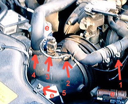
see Fig. 1 :
To gain clearance undo clip (1) & (2) and pull off connector (3).
Move this pipe to the side see (6) fig. 2. to gain more access.
Loosen the clip (4) and remove this pipe from the elbow.
Slip the two electrical connectors and the relay (e) from their clips.
Then undo the 2 bolts (5) which hold the elbow to the car.
see Fig. 2 :
Undo the clip (7) securing the bellows to the throttle housing.
Do the same for the other clip (8) securing the elbow to the air intake.
The elbow and bellows can now be removed from the car. This enables visual inspection of the throttle plate. Mine was very clean so I didn't take the throttle body from the manifold.
The throttle body can be removed by unclipping all the cables and electrical connectors and undoing the 4 bolts attaching it to the air intake (Some of these are not easy to get at, a universal joint extension helps).
The plastic elbow & the bellows can get quite messy and need a good cleaning. Carb cleaner is recommended but WARNING keep it away from the MAF on the air intake and the TPS at the base of the throttle body as you could damage these sensitive components.
Check the gap between the butterfly and the Throttle body wall to make sure its .002"
While it's out, make sure you de-coke the EGR return line where it enters the throttle body, and check to see if the EGR hoses need cleaning.
Refitting
Some people use a gasket material between the throttle body and the manifold.
Torque the bolts (14lb ft) after replacing. If you're using a "gauge" type torque wrench, best look at a longer extension..... one of the bottom is a real challenge to try to meet a torque spec with a large wrench.
Also be careful not to overtighten the clip sealing the bellows to the elbow. When I took mine off the plastic elbow here was squashed allowing lots of air in (see Fig 3). A new elbow is 30 UKP so I heated the kink with a hot air gun and used a curved wood former to push it back into place.
Calibration : As long as you don't move the TPS beneath the Throttle body, You shouldnt see any changes in base idle speed. If you're having any rough or irratic idle problems, then go through the motions of setting the TPS voltage, which is described in Haynes then do the Idle adjustment (see below)
10.6 - Adjusting Idle Speed ( ,
)
Set the throttle plate gap to .002(.05mm). This is the gap between the throttle plate and the wall. To do this right, you should remove the throttle body and clean it with some throttle body cleaner and then set the gap. The throttle body/ plate gets gummed up from the crankcase vent being before the throttle.
After setting the gap, reassemble the throttle body and all parts, clamps, wires, etc.
Warm up car,
ac off,
transmission in park,
turn key off,
Turn key on but don't start car and wait 15 seconds then disconnect connector to iscv.
The iscv is just forward of the throttle body, close to the cruse control bellows.
turn key off,
hook up iscv connector,
turn key on but don't start car...wait 15 seconds,
disconnect iscv connector, (your winding the iscv closed)
leaving the iscv connector disconnected, start the car.
turn the idle speed air bypass screw on the iscv using a 7\32 inch Allen wrench till the rpm is 550 to 600.
Hook up the iscv connector.
You're done.
If the static idle is not set correctly, the rpms will hunt around. The computer is only supposed to raise the idle from base due to a load, so if the base idle is not set right the computer doesn't know what to do, hence the hunting.
10.8 - Oil Change Tip ( ,
)
Underneath the engine near the front is a large plug that looks like an oil drain plug. This plug is dark orange in color and about 2 inches in diameter.This is the access plug for the oil pressure relief valve.
If you remove the front plug, you should replace the crush washer under it. Generally there is less than 1/2 quart of oil in this area. If you drain only from here, there will be several quarts in the back of the pan. It is impossible to completely drain the engine, and the small amount of residual oil will not affect anything but the colour of the oil after the change.
10.9 - Head Gasket ( ,
)
10.9.1 -
Head Gasket failure symptoms ( ,
)
Head Gasket Failure can come with various different symptons including :
Rough running, lack of power
White smoke
Coolant level getting lower with no obvious leaks
Water in oil
The last one often needs to be taken with a grain of salt when checking the quality of the oil by looking in the oil filler. A white emulsion can often appear especially in colder weather and does not necessarily mean your head gasket has failed.
While some cars have exceed well above 100k miles without any problems, others have not been so lucky.
10.9.2 - Head Gasket Replacement ( ,
)
Click here to open one of the pages from the Jag-Lovers photo album including a number of high resolution pictures showing the re intstallation of the head after a gasket change.
It will not replace the Manual but the pictures are really good and it will give you an idea of what's involved.
If you thought that you can't change a head gasket in your own car... this will prove you wrong !
but if you're not up to it, get it down by a pro...
11 - Fuel system ( ,
)
11.1 - Collapsing Fuel Tank Warning ( ,
)
The injection pumps used on these cars has enough power to suck the tank in on itself in the event of a venting problem.
There are the more usual vent problems caused by stuffed check valve, carbon canister, or such. There is also the vent line under the car which can be plugged solid with dried out fuel. What appears to happen is the owners fill the car to the top of the neck, which puts the fuel level above the fuel separator in the vent system. So raw fuel runs in to the vent line and evaporates leaving the sludge behind.
11.2 - Overview of the Fuel Injection System ( ,
)
The engine management system is controlled by the ECU and maintains optimum engine performance by metering the fuel into each cylinder's inlet tract and adjusting the ignition timing angle at the sparking plugs. It correlates data received from a number of sensors located on and around the engine to provide optimum ignition timing and fuel metering parameters relative to engine load and speed. The EM system also controls three features which may have a direct bearing on starting problems:-
1 Fuel pump - to prevent fuel flooding and/or spillage when the engine is stationary with the ignition switch in position 'II'.
2 Cold start control - to ensure there is sufficient fuel in the inlet manifold to create a combustible air/fuel mixture.
3 Idle speed control - to compensate for varying engine temperature and load conditions.
The system also incorporates a 'limp home" facility allowing continued engine operation following certain sensor failures, the specific failure being indicated on the instrument pack.
Fuel is delivered to solenoid operated injectors by the pump operating (via a variable pressure regulator) at virtually constant pressure so that the quantity of fuel injected for a given duration of injector Ĺonĺ (open) time is constant.
Injector operation is by means of an electrical pulse which actuates a solenoid valve in the injector body. The duration of the pulse is determined by the ECU on intake air and engine speed information from the FLOWMETER and CRANKSHAFT SPEED SENSOR.
Correction factors are applied by the ECU to provide two functions which may cause starting problems:-
1 - Cranking enrichment during starting.
2 - Temperature enrichment during starting and warm-up.
Cranking enrichment occurs when the starter motor is activated by INCREASING THE INJECTOR OPERATING FREQUENCY FROM ONE PULSE TO THREE PULSES PER CRANKSHAFT REVOLUTION and is implemented by the ECU in response to an input from the STARTER SOLENOID. This cranking enrichment is only effective up to 600 rev/min.
Temperature enrichment occurs during starting (and warm up) by increasing the injector 'on' time and is implemented by the ECU in response to an input from the COOLANT TEMPERATURE SENSOR. This is the square topped sensor in the thermostat housing. After-start enrichment is provided to supply added fuel during warm up by the ECU which increases the injector 'on' time and decreases the amount of additional fuel supplied.
The ECU interfaces with input/output devices as follows:-
1 FUEL INJECTORS: solenoid actuated
2 IGNITION AMPLIFIER: generates high energy electrical pulses for distribution to the sparking plugs.
3 AIR FLOWMETER: a hot wire sensing device to monitor which inlet manifold air flow for optimum fuel and ignition control.
4 IDLE SPEED CONTROL VALVE: stepper motor driven device controlling the volume of air to maintain correct idle speed.
5 CRANKSHAFT SENSOR: provides engine speed and crankshaft position information to ECU for precise ignition timing and fueling control.
6 THROTTLE POTENTIOMETER: interprets the throttle position.
7 FUEL PUMP RELAY: controls fuel pump!
8 COOLANT TEMPERATURE SENSOR: thermal device which monitors coolant temperature to induce cold starting and warm-up enrichment.
9 SUPPLEMENTARY AIR VALVE: a solenoid actuated device to provide additional air during cold starting.
Other relevant system devices and signals are as follows:-
1 Ignition 'on' sensing: an input taken from contact 87 of the ignition 'on' relay which, in addition to applying power to the ignition coil, energises the main and fuel pump relays through the ECU. A timer is also initiated which, through the fuel pump relay, permits fuel pump operation for approximately 0.5 seconds to ensure the fuel rail is pressurised prior to cranking.
2 Cranking sensing: an input which induces cranking enrichment when the starter solenoid is activated.
The start routine is as follows:-
When the Ignition is switched 'On' power is applied to the various devices through contacts L14-87/30 of the main relay which is energised, via contacts B 17-87/30 of the ignition 'on' relay, when the vehicle ignition switch is in position '11', i.e. when 0 Volts is applied to B 17-85 of the ignition 'on' relay.
Power to the ECU at L3-1 and L2-10 generates a system reset which causes an initialization routine and starts the fuel pump to pressurise the fuel rail prior to cranking. The fuel pump is activated via contacts L5-87/30 of the fuel pump relay which is energised by an output from the ECU at L12-7.
Following the initialization routine, sensor scanning begins to determine engine conditions and to obtain appropriate ignition timing and fuel metering parameters. In addition, the following primary functions are performed:-
1 The stepper motor of the idle speed control valve is driven, via L12-15/16 and L12-18/19, to set the valve at a position suitable for engine starting. Rapid valve positioning is achieved for all conditions by extending or retracting its stem from a mid-travel position restored each time the ignition switch is set to "off'.
2 The solenoid of the supplementary air valve is actuated, via L12-20, to open the valve at temperatures below - 1O░ C. (If you're 14 hours from a Jaguar Dealer, it's either extremely hot or extremely cold)
3 Fuel pump operation is terminated, i.e. the output at L12-7 is removed, after approximately 0.5 seconds to eliminate possible fuel flooding should an injector be stuck in the open position.
4 The exhaust system air pump and solenoid vacuum valve (if fitted) are activated by the air pump relay which is energised, via L12-2, at temperatures between 15░ C and 45░ C.
When the engine cranks fuel pump operation is reinstated and any fault number displayed on the instrument pack fascia is deleted, provided the ECU detects crankshaft sensor input at L13-13 and 14.
As the engine rotates on the starter motor, fuel is introduced into the air flow of the inlet manifold by the fuel injectors which are actuated by the ECU under control of the crankshaft sensor input. Injector triggering occurs, through L12-12, 13 and 25, three times per crankshaft revolution with appropriate correction factors imposed. The ignition amplifier is also actuated at the correct times, through L12-1, to fire the sparking plugs.
When the engine fires, cranking enrichment stops at 600 rev/min, injector pulses occur once per rev, and both warm-up and after-start enrichment occur. In addition, any extra manifold air is delivered by the supplementary air valve which is driven in response to coolant temperature, throttle potentiometer and crankshaft sensor inputs.
Fuel and ignition requirements are calculated at each sensor scanning to maintain optimum engine efficiency. If a sensor failure is detected, a signal is sent to the instrument pack to indicate the failure. The nature of the fault is also stored in ECU memory and is output as a fault number the next time the ignition switch is set to position.
11.3 - Fuel Pump ( ,
)
One thing that might help isolate some of the problems of no start/ cold start, would be to remove the fuel pump relay and jumper pins 30 and 87 in the socket. This should run the pump all the time. Then see if the car starts. Donĺt run it to long that way, but as a test of the no start/ no cold start troubles, it may prove useful.
11.4 - Fuel Injectors ( ,
)
Remove connector from each injector. You should be able to measure about 3 ohms between pins on each injector and open circuit to body.
They are held in by the fuel rail. There are O rings on both ends that are a snug fit (twist and PULL).
Step 1
Undo the fuel lines...on my car there was no pressure after sitting overnight. Obviously, do this job with the engine cold, no smoking, playing with matches or using candles for light. Put lots of rags under the connection points and use 2 spanners, one to hold things still and the other to turn the nuts.
Step 2
Undo all the electrical connections to the injectors and cut any wire ties. Then undo the clamps(plastic) holding the fuel hose to the rail.
Step 3
Undo the 3 or 4 bolts holding the rail to the inlet manifold. Then you can rock it back and forth while pulling it out. Then there are clips holding the injectors to the rail and the snug O rings again.
11.5 - Fuel Non-Return Valve ( ,
)
How to replace the non-return valve on the fuel pump. Always take standard safety precautions when dealing with petrol.
Symptoms :
Car may take a few turns of the engine to start. This is more noticeable when the engine is warm.
No fuel pressure left in the fuel rail when the engine is off.
Fix :
Jaguar part is about $37 and fits into the fuel pump. The fuel pump is located on the rear chassis.
Relieve fuel pressure (in case the old one is not totally shot!)
Disconnect battery.
Jack rear left hand side. Put car on axle stands. Remove left hand wheel.
You should be able to follow fuel line back to the fuel filter (just forward of the wheel arch) and then to the fuel pump which is behind wheel arch.
Get new valve ready with new copper washer on smaller end. Place container to catch petrol below pump.
Original valves required 17mm spanner. Fuel hose requires 19mm spanner. New valve required 19mm spanner.
There is a hex bolt or similar fitting off to the side of the fuel line where it enters the pump. You can use this to hold the pump and stop it turning in its bracket.
Loosen fuel line. Holding the non return valve to prevent it rotating. Undo enough to get it loose then do it up again finger tight to stem the fuel flow (if any). Now hold pump body and loosen the non return valve.
No go back and remove fuel hose. You will still have to hold valve or it will probably unscrew instead.
Don't worry if you see something fall out of the end. You can place pipe up on spring and it won't push out too much petrol. However, valve end will by now be spewing petrol all over the place. Plug end. Hopefully, because you have already loosened it you will be able to unscrew the valve by hand (it's a bit tight to get your hand in so a "dry run" may be in order)
As soon as it's out, drop it and pick up the new one to stem the flow of petrol. The new one WILL stop the petrol coming out as soon as you have a couple of turns made.
Tighten up valve, holding pump body to stop rotation. Then re-attach fuel hose etc.
The purpose of loosening the valve is so that you don't have to spend time trying to undo the valve with fuel leaking out.
The bits that might fall out of the valve is a spring and ball which form the old non-return valve.
11.6 - Replacing Fuel Lines ( ,
)
Buy hose, about 6 ft of 5/16 or 7.9mm, and fuel injection hose clamps.
Let car cool, then undo the coolant recovery tank mounts and move it aside.
Remove the air inlet parts(air flow sensor, elbow, bellows to throttle body along with the heated air tube(that black thing with the wires to it). This gives room to work.
Undo the clamps holding the fuel lines to the rail, the clamp on the cruse control bellows, the plastic clamps under the cruse control bellows and the clip and holder at the bottom where the hoses mount to the hard lines going to the back of the car.
Make a note of which hose goes where, e.g. the hose that goes to the back of the rail goes to the top hard line and the hose from the front of the rail goes to the bottom hard line.
One hose at a time, grind a grove in the metal rings with a dremmel tool or a grinding bit in a drill, then cut the rings with a medium size set of wire cutters. Then cut the hose using care not to get the metal parts under the hose. BEWARE of the fact that the hoses have a rubber insert in the hardline end that will fall out.
Cut the new hose to the same length as the old one then put the clamps on, then put the hose on the metal ends and tighten the clamps.
Put everything back together using the original clamps.
turn key on for 10 seconds, off, on, off then start the car and check for leaks.
11.7 - Throttle Position Sensor ( ,
)
Throttle pot has two identical pots. One for gearbox and other for engine ecu.
One end of each pot is grounded by ECU (about 0V) and other end is supplied with 5V from ECU. Middle should be somewhere between 0V and 5V.
However, the idle setting should be 0.6Volts with 2thou gap on throttle body to butterfly.
It can be adjusted by loosening screws. Pot should move smoothly from 0.6V up to about 4.5V (full throttle).
Some correct settings are:
88 MY is .24 V to .40 V
89 MY is .31 V to .36 V
90 MY and later is .57V to .62 V at closed throttle
11.8 - Purge Valve ( ,
)
Fuel code 89, purge valve.
It's supposed to put a vacuum to the charcoal canister to suck out all those nasty gas fumes that build up in the tank and go into the canister instead of the air.
It's on the drivers side, above the charcoal canister behind the headlight.
The ECM looks at the O 2 sensor for a change when the purge valve is open, no change = check engine.
Purge drive circuit probably means connection or valve malfunction.
The valve can easily be checked by switching ignition on and off. It makes a very loud click. You can also check with 12V directly across terminals which is easier if you haven't got a friend. i.e. two wires to battery but be careful with dangling wires etc.
You can checked valve operation by blowing down the tube off the manifold.
11.9 - Air Flow Meter ( John Pring & Dana Haydel,
)
|
Operation
The mass airflow sensor is a metering device designed to determine the actual ômassö of air entering the engine. It is not a volumetric flow device and it does not require external air density compensation for proper operation. The engine must receive a mass airflow signal to account for changes in air density caused by temperature and altitude. A simple volumetric flow rate signal would be insufficient.
The meter itself, is between the air filter and the inlet manifold (looks like an aluminum tube with a rectangular box on top and a cable harness connecting to it). It is considered a very reliable component typically being trouble-free, and like the engine management computer, should never be condemned without thorough investigation. It performs it primary function of metering the mass of air drawn into the engine using two thermal sensors. These sensors are located within a bypass channel in the MAF sensor. One sensor is termed the ôcompensating coilö and is unheated while the other sensor is called the ôsensing coilö and is electrically heated by the sensor circuitry. The amount of sensing coil current needed to keep the differential temperature between these two sensors constant is directly proportional to engine load (mass air flow).
The compensating coil is always at ambient temperature while the sensing coil is always attempting to create a fixed differential temperature as it is cooled by the air stream. In order to clean the sensing coil, the temperature flashes to 1000 degrees C for one second, four seconds after the ignition is switched off. The engine management computer is monitoring a voltage drop within the MAF sensor electronic circuitry, which is directly related to the current flowing through the sensing coil. This design is factory setup and calibrated. It is non-adjustable for the owner.
Early XJ40s incorporate a manual idle trim adjustment which is a 10 turn, 0-1000 ohm potentiometer built in to the air flow meter for minor idle fuel adjustment, but it works independently of the thermal sensors. Later models have adaptive idle fuel metering and no adjustment or input from the owner is necessary. These MAF internal adjustments, whether manual or automatic, are designed for emissions adjustment. The total available trim for either the manual or automatic idle fuel adjustment is only +/-10% of the nominal injector pulse duration at idle. Manual trimming is not recommended unless the owner has access to an emissions analyzer.
Functional Checks
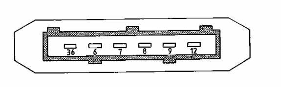
Located on the left side of the MAF sensor is the six pin, rectangular electrical connector. This connector can be problematic. It cannot be over-emphasized that the engine management system utilizes low voltage control signals. These signals are subject to faults and high resistance joints caused by corrosion. To overcome this known problem, later models of XJ40s were equipped with gold plated connections. The connector is held in with wire clip. If you push up on the wire clip from underneath, the connector can be removed from the sensor.
Electrical conductivity problems may be resolved by simple cleaning of the connector pins using a quality electronic component cleaner. It may be necessary to bend each male connector pins (in the MAF sensor housing) slightly to insure good connectivity. Pin layout is according to the figure below. Pin 36 is towards the front of the car. Pin identifiers may change from model to model, but the basic function remains the same.
Typical readings on certain conditions:
36 & 6 : Grounds
7 : ECU Ground
8 : Empty Connector
9 : 12 VDC Supply
12 : ECU Supply 5.0 VDC
Ignition on MAF disconnected (no start) Ignition on MAF connected (no start) MAF connected engine running @ idle (~750RPMs)
7 <1V (leakage) 7 >1V (leakage) 7 ~1.2V to 1.4V
9 Battery voltage 9 Battery voltage or slightly less 9 >Battery voltage due to alternator operating
12 ~ 5V 12 ~1.85V 12 ~1.8 to 2.5V
Diagnostics:
Battery voltages on pin 9 that deviates significantly from the chart need to be investigated further and repairs made.
Note: Should the battery be disconnected the engine management will need to re-learn the base idle. This ôre-learningö is automatically achieved by operating the engine at normal coolant temperature and driving for a distance > 50 yards. The engine may stall at idle once or twice until the adjustment values are accepted and stored within the ECU RAM.
Pin 7 readings < 1.2V can produce poor running conditions and if lower possibly no start. A voltage of <0.2V or > 4.5V is will generate a diagnostic test code (DTC 12). Refer to Fault Code List for other diagnostic help with this fault.
Pin 12 reading will typically increase towards 5V as engine revolutions are increased. This reference voltage is from the ECU.
Bench Test (Circuit Checks) for MAF Sensor:
1) Remove the electrical connector from the MAF sensor.
2) Connect a 12VDC power source (battery) to Pin 9 (+) which is normal 12 VDC supply to the MAF sensor and Pin 36 (-) which is normal ground for the MAF sensor. Ensure the power supply positive is connected to Pin 9 and the negative is connected to Pin 36. Do not reverse power supply polarity.
3) Connect a quality digital multi-meter setup to monitor voltage to Pin 7 (+) and Pin 6 (-). Ensure multi-meter positive test lead is to Pin 7 and negative test lead is to Pin 6. If multi-meter polarity is reversed, voltages will indicate negative but the absolute values will be correct.
Test 1 : Air meter stationary with no flow
Test 2 : With a blast of air in the direction of flow
Ignition
on MAF disconnected (no start) |
Ignition
on MAF connected (no start) |
MAF connected
engine running @ idle (~750RPMs) |
7 <1V
(leakage) |
7 >1V
(leakage) |
7 ~1.2V to
1.4V |
9 Battery
voltage |
9 Battery
voltage or slightly less |
9 >Battery
voltage due to alternator operating |
12 ~ 5V |
12 ~1.85V |
12 ~1.8 to
2.5V |
Diagnostics:
Battery voltages
on pin 9 that deviates significantly from the chart need to be investigated
further and repairs made.
Note: Should the
battery be disconnected the engine management will need to re-learn
the base idle. This “re-learning” is automatically achieved
by operating the engine at normal coolant temperature and driving
for a distance > 50 yards. The engine may stall at idle once or
twice until the adjustment values are accepted and stored within the
ECU RAM.
Pin 7 readings
< 1.2V can produce poor running conditions and if lower possibly
no start. A voltage of <0.2V or > 4.5V is will generate a diagnostic
test code (DTC 12). Refer to Fault Code List for other diagnostic
help with this fault.
Pin 12 reading
will typically increase towards 5V as engine revolutions are increased.
This reference voltage is from the ECU.
Bench Test
(Circuit Checks) for MAF Sensor:
1) Remove the
electrical connector from the MAF sensor.
2) Connect a 12VDC
power source (battery) to Pin 9 (+) which is normal 12 VDC supply
to the MAF sensor and Pin 36 (-) which is normal ground for the MAF
sensor. Ensure the power supply positive is connected to Pin 9 and
the negative is connected to Pin 36. Do not reverse power supply polarity.
3) Connect a quality
digital multi-meter setup to monitor voltage to Pin 7 (+) and Pin
6 (-). Ensure multi-meter positive test lead is to Pin 7 and negative
test lead is to Pin 6. If multi-meter polarity is reversed, voltages
will indicate negative but the absolute values will be correct.
Test
1 : Air meter stationary with no flow
|
Test
2 : With a blast of air in the direction of flow
|
Volt
readings |
Diagnostics |
Volt
reading |
Diagnostics |
0.4
+0.2V |
OK |
Rise
to 1.5V then returns to Test 1 |
OK |
0V |
Output
open circuit |
0V |
Output
Open circuit |
>
0.7V |
Output
Drifted Module inoperative. Sensors(s) detached |
Same
voltage as in Test 1 |
Module
inoperative |
|
|
>
5V |
Sensor(s)
wire detached
Calibration drifted |
12 - Fault Codes ( ,
)
12.11 - Fuel Fail 11, idle trip signal out of range ( Brett Gadzinsky,
)
Fuel fail 11 is for the idle trip signal out of range. It has nothing to do with the throttle or the throttle position sensor.
The idle trim signal is built into the MAF (Mass Air Flow sensor). It is used to set the base idle mixture before oxy sensor correction. Normal output signal is about 2.5 volts and does not vary. Its set at the factory, and never needs adjustment.
It was used up to 1993 year cars, then Jaguar used an adaptive system.
The actual adjustment pot is built in the maf sensor, but is not really part of it, that's just where Jaguar (or bosch) stuck it. Since you cant get at it, its behind a sealed plug, it cant really go wrong, and your problem is likely from a dirty connection on the maf sensor.
The maf sensor is critical on how the engine runs, and its connections are sometimes abused by the connector hitting the coolant tank, make sure the connector is clean and tight. The first step would be to clean the connector using contact cleaner or WD40 , and then add a dab of dielectric grease to the contacts before reassembling. The parts stores sell the grease. You may have to disconnect the battery or pull the ECU fuse to clear the code.
If this doesn't fix it, the throttle pot itself may have failed. Cleaning the throttle body with solvent and getting it in the throttle pot can cause it to fail. The check procedure is nicely described in Haynes.
12.12 - Fuel Fail 12 : Mass Air Flow sensor out of range ( Brett Gadzinsky,
)
Output below .2 volts or above 4.5 volts engine rpm 400 to 3000 rpm for 5 crankshaft revolutions.
If FF 12 is flagged, ecu uses throttle position sensor input for engine load indications instead of the maf sensor.
Possible faults :
- Old style unsealed relays for EMS main 1993 year cars and up.
- Open or short in wiring between maf and main ecu.
- High resistance connection between maf and ecu (dirty connector at maf sensor).
- Open circuit in wiring from main relay power (12 volts) to maf.
- Bad maf sensor.
The maf sensor is in the air intake tract, after the air filter and before the throttle. It uses air flow through a side port to cool and change the resistance of sensors, corrected for ambient air temps to measure the air flow through the intake tract. Since it has no moving parts, its reliable, but suffers from having its connector in a bad spot. Its also subject to contamination of the sensors by any type of liquid.
Inside the sensor is a circuit board with voltage regulators, and a lot of parts and IC chips. On the 1988 to 1992 year cars, the base idle mixture trim is built in, but not part of the actual maf circuitry. Sensors to 1991 had a separate ground wire to a stud on the maf.
To test the maf, warm the car up to operating temps. At idle in park (about 740rpm) the output signal should read 1.2 to 1.5 volts, the higher the reading, the higher the indicated air flow. If your maf sensor puts out about 1.2 volts at idle, it is indicating a low air flow, so will adjust the injector pulse time down
to keep the mixture in range. 1.2 volts is on the low side of a normal reading and may cause problems unless you are at a high altitude.
If you have a vacuum leak, the INDICATED air flow into the engine will be low, the ecu will reduce the injector pulse, and you will have a lean mixture and a poor idle.
To test the high air flow, measure the output voltage with the car in drive, full throttle, foot on brake. Only do this test for a very short time, and use great care the car does not get away from you. At full throttle the maf should read about 3.0 to 3.3 volts. This is the torque converter stall reading, actual full throttle high rpm will indicate higher.
The maf sensor has a lot of input on the mixture and indicated load range the engine is operating at. A small change in the signal denotes a large change in mixture.
Under normal operating conditions, the maf sensor and the coolant temp sensor set the mixture and the way the engine runs.
12.14 - Fuel Fail 14 : coolant temp sensor out of range ( Brett Gadzinsky,
)
Conditions for flagging :
After cold start, signal to ecu under 3.53 volts after 6 minutes.
Normal engine operating temp, Signal decrease of .7 volts or greater in 196 milliseconds.
Normal coolant temp sensor out of operating range, Under .1 volt, above 4.9 volts for 64 milliseconds or longer.
If FF14 is flagged, the ecu defaults to 80F.
Possible faults:
- High resistance connection between the sensor and the ecu (dirty connection at coolant temp sensor)
- Open or short circuit in wiring between coolant temp sensor and ecu.
- High resistance ground circuit in ecu circuit.
- Defective engine thermostat.
- Defective coolant temp sensor.
The coolant temp sensor has 2 wires, and is located close to the engine thermostat. They very rarely fail.
The coolant temp sensor is used to control a number of functions:
- Cranking enrichment,
- Warm up enrichment,
- Acceleration enrichment,
- Air injection,
- Idle speed control,
- Exhaust gas recirculation,
- Evap system canister purge.
To test the coolant temp sensor, measure the resistance between the two terminals hot and cold.
14F 9200 ohms
32F 5900 ohms
50F 3700 ohms
68F 2500 ohms
86F 1700 ohms
104F 1180 ohms
122F 840 ohms
140F 600 ohms
158F 435 ohms
176F 325 ohms
193F 250 ohms
212F 190 ohms
12.16 - Fuel Fail 16 : intake air temp sensor out of range ( Brett Gadzinsky,
)
Conditions for flagging : signal to ECM under .1 or over 4.9 volts for 69 milliseconds. Default setting 86F if FF 16 is flagged.
Possible faults :
Dirty connection at air temp sensor,
High resistance or short between air temp sensor and ecu,
Bad intake air temp sensor.
The intake air temp sensors function is to retard the ignition timing during intake air temp rise to prevent detonation. The intake air temp sensor resistance reads he same as the coolant temp sensor.
14F 9200 ohms
32F 5900 ohms
50F 3700 ohms
68F 2500 ohms
86F 1700 ohms
104F 1180 ohms
122F 840 ohms
140F 600 ohms
158F 435 ohms
176F 325 ohms
193F 250 ohms
212F 190 ohms
At high engine loads, the air intake temp sensor retards the timing 2.25 degrees every 10C above 86F (30C), at light loads, it retards the timing starting at a higher temperature. It has NO effect on mixture.
The intake air temp sensor is located on the top of the elbow.
12.17 - Fuel Fail 17 : TPS out of range low ( Brett Gadzinsky,
)
Conditions for flagging : signal to ecu under 250 millivolts for 64 milliseconds.
The throttle position sensor is used by the ecu for :
- Idle speed control,
- Ignition idle strategy selection,
- Overrun fuel cutoff,
- Idle fuel trim (1990 to 1992)
- Main fuel metering strategy,
- Main ignition strategy,
- Acceleration strategy,
- Deceleration leaning,
- Full load enrichment.
Default settings while FF17 is flagged is 1.5 volts, and all throttle position sensor functions do not operate.
Possible faults :
- High resistance at throttle position sensor or ECM,
- Short or open circuit in wire harness between tps and ecu,
- Loose or incorrectly adjusted throttle position sensor,
- Defective throttle position sensor (worn).
On the 1990 to 1992 year cars, the tps has two separate sensors in one housing, one does the engine, the other does the transmission. After 1992, one sensor talks to both the engine and trans. On the early cars, to about 1993, the sensor is under the throttle and is turned by the throttle shaft.
Various year cars had different idle voltage settings :
87-88 .24 - .40
89-90 .31 - .36
90 and up .57 - .62
Full throttle should read about 4.5 volts.
Be careful to prevent anything getting in the tps while cleaning the throttle out...don't spray any cleaners in the throttle or the gunk will wash into the sensor.
12.18 - Fuel Fail 18 : TPSensor and MAF Sensor ( Brett Gadzinsky,
)
High throttle position signal, low air flow signal : the ECU looks for a combination of high throttle signal and low air flow signal that can not occur in a normally operating system.
Conditions for flagging :
- Throttle position sensor 2.25 volts or greater,
- Engine load site 3 or lower (low maf sensor output)
Response time : 5 engine revolutions.
Default settings: ignore throttle position sensor.
Possible faults:
- High resistance connection to ECU or throttle position sensor,
- Restricted air intake,
- Restricted exhaust,
- Low fuel pressure (low engine power)
- Ignition fault (low engine power)
- Engine mechanical fault,
- Short or open circuit between ECU and maf sensor,
- Incorrectly adjusted throttle position sensor,
- Bad throttle position sensor,
- bad maf sensor.
Check tps output signal, maf sensor output signal, engine vacuum readings.
12.19 - Fuel Fail 19 : Low Throttle Position Sensor ( Brett Gadzinsky,
)
High air flow signal, the ECM sees a combination of closed throttle and high intake airflow signals.
Conditions for flagging FF19:
- Throttle position sensor at idle,
- Engine load site 13 or higher,
- Engine rpm,s 1000 or higher for 5 or more crankshaft revolutions.
Default with FF19 flagged: ecu ignores throttle sensor and sets 1.5 volts, idle functions are disabled.
Possible faults:
- High resistance connection to ecu, maf sensor or throttle position sensor.
- Water in MAF sensor,
- Short or open in maf and throttle sensor wiring,
- Bad throttle position sensor.
Clean and wd40 the connections to the tps and maf sensors. Measure the throttle position sensor resistance at idle and as you open the throttle.
12.22 - Fuel Fail 22 fuel pump control circuit ( Brett Gadzinsky,
)
ECU flags FF22 if the signal to the fuel pump relay indicates open or shorted.
Conditions for flagging FF22:
- Ignition on,
- Fuel pump operating,
- indications of open or shorted fuel pump relay coil circuit.
- Response time 600 milliseconds
Possible faults:
- Low battery voltage,
- Poor ecu power feed or ground connections,
- Short or open circuit between ecu and fuel pump relay,
- Short or open circuit to oxy sensor heater relay (1993 and up),
- Loose connector pins (li18) 6 way PM4 yellow connector under air cleaner (1991-1992)
- Bad relay,
- Air pump relay circuit fault.
If the fuel pump does not work, but FF22 is NOT flagged, its the relay (contacts), the connections at the fuel pump, or a bad fuel pump.
12.26 - Fuel Fail 26 oxy sensor feedback lean ( Brett Gadzinsky,
)
Fuel fail 26 is . As the engine gets partly warmed up, it stumbles and sets the code. The code will clear when the trouble does, on the next restart.
Possible faults for a FF26 are :
- Low fuel pressure (plugged filter, weak pressure regulator on fuel rail, plugged system)
- Intake manifold air leak (vacuum hoses, intake manifold gasket, evap system hose rot, egr pipe rusted out, problem with air injection system (leaking valve).
- Ignition misfire, (bad plug, wires, cap, rotor)
- Purge valve stuck open (vacuum leak in evap system)
- Oxy sensor fault (not common)
- Bad maf sensor or connections.
Best to start with the ignition system : If the wires, cap, rotor are old, replace them, along with spark plugs.
The catalytic converters may eventually melt plugging the exhaust if the car is ran with the FF alarm on, so don't ignore it just because the engine runs ok.
12.3 - Code 3, Coolant temperature sensor. ( ,
)
Code 3 says Coolant temperature sensor.
On the 1990 the codes are different. However, on my car there are two coolant temperature sensors located almost next to each other on the thermostat housing (top front of engine).
One drives dashboard temperature gauge via dash board computer. Other is used by ECU. The latter is the problem. You can find out which is which by disconnecting each and seeing if temperature gauge goes wacky (warm engine required).
Dashboard gauge sensor has just a single wire and other has connector. If the connections look OK (e.g. remove and clean). You can measure resistance with meter. Do when engine is cold and hot. At 25C (hot day-cold engine) it should be about 2500 Ohms. Hot engine (80C) about 300 Ohms
12.39 - Fuel Fail 39, EGR temp sensor circuit ( Brett Gadzinsky,
)
The ECM looks for a low egr temp signal when the egr valve is closed, and a high temp signal when the egr valve is open. The ECM also looks for an over temp signal when the egr system is enabled.
The egr temp sensor is located behind the throttle in the bottom of the intake manifold, close to the exhaust gas entry point.
The egr temp sensor is a negative temp coefficient thermistor :
Resistance decreases with temp increase.
Resistance, 122f 560,000 to 710,000 ohms.
Resistance, 212F 76,000 to 94,000 ohms.
Conditions for flagging FF39 :
- Engine coolant temp above 180F,
- Throttle position within expected range for engine speed,
- Engine speed 1700 to 3000 rpm,s,
- Load site range 2 to 7,
- Egr enabled, indicated temp greater than 525F for 64 milliseconds,
- EGR enabled, indicated temp under 212F for 60 seconds,
- EGR disabled, indicated temp greater than 122F for 5 minutes.
Possible faults:
- Blockage in EGR transfer pipe between egr valve and intake manifold,
- Blockage in intake manifold EGR adaptor port (90% of problems),
- Disconnected, leaking, blocked, pinched vacuum hose between,
- EGR valve and the egr vacuum solenoid,
- Defective EGR solenoid valve (stuck),
- Defective EGR valve,
- Defective egr temp sensor,
- Open or short in egr temp sensor wiring.
Most modern cars use exhaust gas into the intake tract to reduce combustion temps and NOx because exhaust gas is inert. It has no fuel or oxygen.
The EGR system ONLY operates when the engine is up to temperature and the engine is under light or moderate loads.
12.44 - Code 44 ( ,
)
The code 44 and 26 have some overlap. Code 44 means that the oxygen sensor is signaling the computer that the fuel mixture is bad - too rich or too lean. The car can then not run in closed loop mode, and the VCM after a while ignores the oxygen sensor and goes to a default mode. If the sensor itself was bad, the car would probably run just fine, but use more gas, although in some cases will run irregularly. More likely you have a true, too lean or too rich problem.
The first step in diagnosis is to idle the car until the car runs rough or the error light is activated. Then, using a DIGITAL multimeter, measure the output of the oxygen sensor by back probing it while still connected - do this at the junction of the wire from the sensor on the right (US) fender well. It will oscillate rapidly under normal conditions from .9 to 2v. If mixture is too lean it will read very low all the time. Check with a manual for the actual voltages, these may be incorrect, or vary between models.
TOO LEAN: If you determine that the mixture is too lean, then you have either fuel starvation or an intake air leak. If the car idles OK but has loss of power at speed, then you likely have fuel starvation. An intake air leak will cause bad idle but will be less noticeable at speed.
TOO RICH OR AMBIGUOUS: This could be a sensor problem (air mass sensor, throttle pot or others), but most likely an ignition problem. This may well be the most common cause for code 44. Before you do anything you check the ignition, try just replacing distributor cap and rotor , spark plug wires, and spark plugs. - Its cheap and easy and maintenance anyway. It might be possible that a misfire resulted in fouling of the oxygen sensor (code 26), then when replaced with a new one you got code 44.
Conditions for flagging...
- Engine coolant temp above 167F,
- Throttle position under 3 volts,
- 450 engine revolutions in a row no oxy sensor switching.
Possible faults:
- Fuel pressure fault,
- Stuck open purge valve,
- Poor ground connections,
- Poor oxy sensor ground connection,
- Open or short in oxy sensor heater and/or output circuit,
- Defective air injection pump or circuit,
- Intake air leak,
- Plugged fuel injector (or bad electrical connection)
- Defective maf sensor.
Do a hot engine vacuum reading. At about sea level, you should get roughly 20 inches of vacuum at hot idle.
You can have a vacuum leak in many impossible to see places....
- The egr system/pipes/valve,
- The vapor recovery system...at the vacuum port under the throttle (nipple falls out of manifold), at the charcoal canister hoses in the front air dam, intake manifold,
- Crankcase vent system, etc.
After that, check the fuel pressure and the injectors. You can unbolt the rail from the intake manifold and remove it, then remove each injector and check the intake screens. At that time, you can also remove the fuel pressure regulator and using air pressure, test the pressure set point. Should be 44 psi without any vacuum on the vacuum port. Fuel pressure typically runs between 32 to 44 psi, 44 psi full throttle (no vacuum), 32 psi with 20 inches of vacuum...
Ignition problems typically set a ff26. During a severe miss, fuel and air is dumped into the exhaust, setting the FF26. For FF44, the engine seems to not be able to get enough gas into the mixture. This means a shortage of fuel, or an abundance of air.
When heated with a torch till its hot and slightly glowing, the oxy sensor should put out about .9 volts. Voltage reading will vary around as you move the torch, but if it gets up to .9 volts, its ok.
I doubt they fail often, typically when the heater gets erratic. They have to be hot to work, so if they don't get hot, they don't work. The relay that powers the heater also runs the fuel pump.
You could have a big vacuum leak when the ecu operates the canister purge. The ecu will open the solenoid to purge the fuel vapors in the canister after the engine is up to at least 93F and above idle.
12.48 - Fuel Fail 48 : Idle Speed Control Valve ( Brett Gadzinsky,
)
The idle speed control valve adjusts the idle speed, something abnormal going on with the idle speed will be a sympton of problem as the ECM looks for the ISCV far out of position at idle.
Conditions for flagging ...
Throttle position...at idle
Engine coolant temp above 186F
ISCV full open
Engine speed lower than normal.
Or,
Engine coolant temp less than 94F
ISCV full closed,
Engine speed greater than normal.
Possible faults...
- Low battery voltage,
- Loss of ECM memory power,
- Loss of ECM ground connection,
- Badly mis adjusted idle bypass screw,
- Badly mis adjusted throttle,
- Air leak past ISCV,
- Low engine power at idle when hot,
- Stuck ISCV,
- Blocked ISCV port or hose.
The idle speed control valve adjusts the idle speed from a base idle speed, both up and down. Say the base idle speed is set for 500 rpm before the ISCV adjusts it...it can move the idle down 30 steps, and up 200 steps.
The ecu learns the correct default position and stores it if you start the engine cold, let it warm up fully without stepping on the gas, then drive off.
If the throttle is messed with, or the engine has a big vacuum leak, the ISCV will be at the end of its adjustment, or not be able to get the idle speed low enough, and set codes.
Many times, people who don't know fuel injection cars try to adjust the idle speed at the throttle. This will do nothing but cause problems till the ISCV runs out of adjustment, then the idle speed will start changing.
I would guess you just have to have the idle speed set up, or a vacuum leak fixed and all will be well.
13 - Accessories and Misc ( ,
)
13..5 - Leaky Boots and Damp Carpets ( ,
)
Places to check for that annoying boot leak:
Plastic trim mounting holes: squirt some silicone around the holes.
Fuel filler gasket: Damage to the rubber, and/ or a clogged or deteriorated drain tube, can often be hidden under the crap which tends to collect in there. (This can also resulted in occasional fuel odor in the boot.)
Antenna grommet.
All are pretty easy to diagnose with a little water on a dry day.
A not impossible situation, if a leaky boot is not noticed is some mould on the carpet. Give it a clean and hang it in the sun. The UV light kills off the mould and the fresh air should remove the smell.
13.1 - Windscreen Washers ( ,
)
Leaking Washer Bottle
Not uncommon, some crack along the bottom. The washer bottle is in two parts, with a rubber ring seal between the two.
You have to remove the plastic underwing protector to get at it. Watch out when getting a replacement - there are different types. It's not impossible to fix the bottle with fiberglass should you have problems getting a replacement.
Remove the two 10mm attachment bolts that hold the upper reservoir in place, twist it a little and it should pop out. The problem is a hardened ĹOĺ ring which doesnĺt seal properly.
Incidentally the lower reservoir holds almost a gallon of washer fluid on the headlight power wash models.
13.10 - Using the Shop Manual CD ( John Pring,
)
1) Load the XJ40 Repair Manual CD ROM.
2) Click on the ôScanFile Retrieveö file from the Start Programs menu.
3) When the User Screen comes up, click on the ôFolderö icon at the upper left side menu bar.
4) When the Dialog Box comes up, go to the bottom and click on the CD drive. A series of 13 total volumes will be listed on the CD.
The 1st Shop Repair Manual (8 Volumes) is designed for the 1990 -1994 XJ40 Model Years. They include the 2.9L, 3.2L and 4.0L engines.
The 2nd Shop Repair Manual (5 Volumes) is designed for the late '87, '88, and '89 XJ40 Model Years. They include the 2.9L and 3.6L engines.
5) Double click on desired Repair Manual ôVolumeö, a dialog box comes up with search options.
6) Click "Begin Search". A new dialog box will come up with a listing of the pages in that section. The Table of Contents image (hidden) will be located behind the listing of pages. Icons will become active on the left side menu bar.
The first page of the selected Volume is a title page with a listing of the sections. The next few pages are a detailed listing of that Section's contents. The remainder of the Volume is the technical information and detail.
7) Highlight the entire Volume by using the right mouse button.
8) Choose "Select", then "All". All the pages will turn yellow.
Once you have highlighted the entire Volume, you have the option of walking through the Volume page by page by clicking on the ôBlue Book with Red Arrowö icon or going directly to the page desired by scrolling down and clicking on it.
13.2 - Windscreen Wipers Park ( Peter Crosby / Dave Hurlston,
)
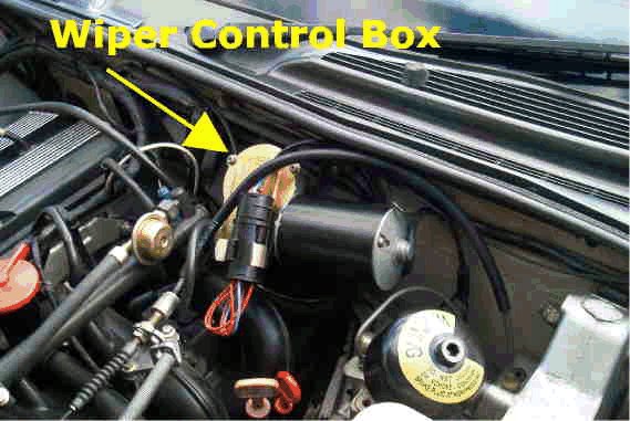
fig. 1
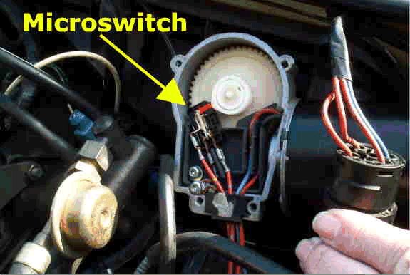
Fig. 2
|
This is a description of the wiper park function on the early XJ40s. I have to assume the later cars work the same way.
There are 3 modes for the wiper:
1. High and low speeds.
2. Single wipe.
3. Intermittent wipe.
There are 3 power connections to the wiper motor itself. One each for high and low speeds (primary power) and the other is for parking (parking power). Control and application of each is handled by the car's central microprocessor (ECU), which takes input from the wiper stalk switch, in conjunction with the wiper logic unit (WLU).
When you turn on high or low speed the wiper motor uses the primary power connections to supply power to either the low-speed or the high-speed motor windings. When you turn them off, the parking power comes into play. More about this below.
When you pull the stalk for a single wipe, you supply power to the motor through the primary power connection (low-speed) as long as you hold the stalk pulled toward you. When you release it, that connection is broken and the parking power again comes into play.
When you enable intermittent wipe, the ECU pulses the primary power via the WLU to move the wiper out of the park position, then releases that power and, again, the parking power engages. If you listen carefully, you can hear the primary power connection relay in the WLU click on and off. The interval for intermittent wipe is not, at least in the early cars, adjustable.
Now, how does the parking power work? This power goes through an undocumented inline fuse behind the passenger's side underscuttle. The fuse is rated at 5 amps. The wiring is such that power is only supplied to the park circuit when it is not supplied through the primary circuits. The power is applied through a switch (park switch) which is in the wiper motor gear box and rides against an adjustable cam plate. The position of the cam plate determines the park position of the wiper.
So.....
1. When you go from low speed or high speed to off, primary power is disconnected and parking power is applied to the park switch. With the contacts closed (non-park position of the wipers) the motor is run until the wiper reaches the park position and the switch opens, disconnecting power and stopping the wiper.
2. When you single wipe the wiper (pull the stalk to you and release it), power is applied through the primary power connection until you release the stalk. At that time, parking power is applied through the park switch until the wiper reaches the park position and the switch opens. Then the wiper stops.
3. When you use the intermittent mode, the ECU pulses the primary power relay in the WLU to move the wiper off the park position and close the park switch. Then primary power is disconnected and power is applied through the park switch until the wiper reaches the park position and the switch opens. Then the wiper stops.
Typical problems are:
A. Wiper stops immediately, wherever it is on the windshield, when primary power is disconnected.
This is usually caused by the inline fuse blowing (often because the wiper was stuck). If it has not blown then look for an open circuit between the fuse and the motor. If it blows repeatedly, look for a short in the wiring, a gummed up or bad wiper motor, or a bad park switch.
This can also be caused by a badly miss-adjusted park switch, such that the contacts in it are always open. Adjust the switch so that the contacts are closed when the wiper is not in the park position and open when it is.
B. Wiper parks, but in the wrong place.
This is usually caused by a bad or miss-adjusted park switch or the cam plate the switch rides against. The switch may not work correctly if it is loose such that the cam will not open and close the contacts. The cam plate may have shifted causing the wiper to stop in the wrong place; it can be re-positioned.
However, it might also be that the wiper itself is improperly installed on the motor output shaft. Check and adjust the switch and cam plate first. Then, if necessary, loosen the nut holding the wiper arm to the shaft, work the arm free from the conical shaft, position the blade on the windshield in the desired park position, and re-tighten the nut.
C. Wiper runs all the time.
The problem is that the park switch contacts are never opening. It is caused by a bad or miss-adjusted switch.
Note: pulling the in-line fuse out will allow you to manually park the wiper until you have the time to pull the top plate on the wiper motor and correct the problem.
If the wiper operation is erratic, and stops at different places on the windshield, the problem is often a faulty micro switch.
Access to the micro switch is easy. Picture 1 shows the wiper motor and the control box on the left off the motor. Picture is for a 1990 XJ40, Left Hand Drive.
Unclip the connector and move out of the way. Remove the 4 torx screws that hold the cover plate in place together. You will see the micro switch inside. Picture 2 shows the micro switch, The switch cover has been pried off for access to the contacts.
WARNING. There is 12 volts on the micro switch at all times. If you touch the switch contacts, the wiper may cycle, so be prepared. You may prefer to disconnect the battery ground before going any further.
The switch can often be cleaned, but if the contacts are really badly pitted, it should be replaced. Electronic stores are a source for a replacement.
To clean the switch, use contact cleaner and then a thin piece of cardboard. Draw the cardboard between the contacts while applying gentle pressure to close the contacts on the cardboard.
Test the wiper operation, and if OK, put everything back together.
The park switch is a rather standard microswitch and should be available from most electronic supply stores. Doug Bernard (dbernard@datecinc.com) offered the following part number and supplier information: Brand: OMRON Part#: V-16-1C24 (Second xref number is 3189RA2) It can also be purchased from the Jaguar dealer or parts supplier using the part # JLM-011332 (thanks Don Czapski czapski@sprynet.com) and costs less than $20 (USA).
13.3 - Seat Belts ( ,
)
All Passive Restraint motor and winch assemblies are warranted for life. (This may vary from country to country).
13.4 - Alternator etc. Belts ( ,
)
OE manufacturer is DAYCO a commonly available brand in the US.
13.6 - General Leather Care and Info. ( ,
)
CONNOLLY Brothers do sell touch-up dye but it's likely to cost you more than $30. In the UK, if you send a small section of the leather they supply the correct match. They also advertise a range of leather care products for cleaning etc. Their products used to be available from Hirsch's in Newark, N.J. who offered a similar colour matching service.
Over the years Jaguar have used less and less leather and more synthetics in the upholstery. Although the Daimler VDP has what is called a "full leather interior", comparison with the interior of a Bentley or an Aston Martin reveals a wide difference in interpretation of this phrase. Lower down the Jaguar range practically the only leather in the XJ40 is on the seat facings.
A major change in leather finishing occurred in the 1960's. Since then new lacquers composed of ketones, polymers and plasticisers have been used in leather finishing.Virtually all hides now are painted and surface protected.
The two main hide suppliers are Bridge of Weir and Connolly. Most car manufacturers claim to use Connolly hide probably because it's the best known name but I've seen both types in Jaguars.
The main difference between Bridge of Weir and Connolly is that Bridge of Weir is dipped in dye vats, then given a final finish, whilst Connolly is painted. The way to tell the difference is to look at the back of the hide. If the reverse is the same color as the front it's Bridge of Weir; if not it's Connolly. Connolly is just a brand name, not a type of hide and their hides are no better than an equal grade of any other hide.
13.6.1 - Routine Maintenance ( ,
)
Leather may be the ultimate upholstery material but it takes more maintenance than synthetics. It has three main enemies:-
1. Abrasion
2. Grease/tar based stains
3. Drying out
Modern leathers are finished with easy care finishes which means that a wipe over with a damp cloth is all that is normally necessary, followed by an application of Hide Food.
Cleaning is fundamental to both regular care and repairs. The process of washing helps keep the leather supple. For a thorough job, the seats need to come out but, if not, remember those electric motors and heating elements inside! The routine cleaning sequence is:-
1. wash with Saddle Soap and a damp cloth or a brush if heavily soiled
2. wipe off all soapy residue with a damp towel;
3. wait about 45 minutes then buff with a towel.
4. remove any grease spots with a naphtha-based cleaner followed immediately by washing.
5. allow to dry properly before proceeding.
Next, consider care of the leather. An Oil Dressing such as LEXOL can be used but not many of the leathers used since the 1960's are porous.
HIDE FOOD is a more effective treatment on today's leather. The term 'Hide Food' is probably misleading as it suggests a feeding action. Modern upholstery leather does not require to be fed and most hide foods are actually wax emulsions which leave the surface soft and supple whilst the thin protectivecoating of wax helps repel dirt.
If you're recolouring, and therefore removing/stripping the old lacquer finish, then a hide food is ideal to make it supple. These dressings are about 90% soap and 10% oil. Due to the limited breathability of many modern leathers, however, hide food's effect is limited to surface dressing on finished hide.
13.6.2 - Recolouring ( ,
)
This is cheap on materials but high on labour. The only satisfactory way to obtain an even depth of colour and finish is to treat the entire seat or (at minimum) the panel section. Spot repairs are always visible.
There are many Refinishing Kits on the market which fall into two types:-
1. water-based
2. lacquer/resin-based emulsions
Your Jaguar leather was originally finished with the second type which is what Connolly supply for refinishing. The lacquer/resin-based emulsions are also less likely to come off on your clothes in hot weather - not that anyone ever has problems with the air conditioning, of course!
Leather must be kept supple enough to take the refinishing process. With regard to renovation it is absolutely essential that the surface of the old leather is prepared properly by cleaning followed by degreasing with a solvent. This is absolutely essential if the new colour coat is to adhere properly. Spray application is preferable to hand application as an excess build up of lacquer emulsion caused by the latter can produce unevenness and a cracking effect at a later date.
1. Remove the seats.
2. Clean thoroughly with saddle soap.
3. Solvent degrease
4. Abrade with fine wet & dry
5. Apply the dye.
After thirty minutes drying time, the result should be a smooth, even, natural finish, with good color consistency, on all except the most worn areas. A second coat, applied three hours later will produce a consistent color and high-quality finish.
Depending on the seriousness of your problem, thorough cleaning and/or partial re-colour should restore the original finish.
13.7 - Engine bay cleaning ( Brett Gadzinsky,
)
We all like to see a clean engine compartment, especially in a Jaguar where the engine is something to proud of; it also makes working on the car a more pleasant experience. Unfortunately, as we all found out the hard way at one point or another, using degreaser and a lot of water comes at a price like the car not starting or running rough.
Generally, only a wet cap/wires/plug holes will stop the engine from starting in MOST cases.
NEVER wash the engine then park the car for a week; this is a VERY bad idea. The best way to clean your engine is to run it till it's warm, then spray something like Armorall or son of a gun all over everything except the oxy sensors, then go for a drive...one that gets the engine and engine bay full hot, to bake out any moisture.
Very bad idea to spray degreaser on the engine, and .....
* Not remove ALL the electrical connectors and relay sockets and spray wd40 on them,
* Not run the engine till its full hot for some time (go for a drive!),
* Not use silicone spray of some sort.
If you do degrease the engine with those sprays, and the spray sits inside of a relay socket, a connector, etc, it will
erode away the contacts over time.
Use the spray stuff the first time you clean the engine, and from then on use the leftover car wash soap and water.
With the wd40 and silicone spray, you can actually wash the engine while it's running, without it missing a beat. Both the wd40 and the silicone spray water proof everything. Dielectric grease is also good for most connectors, but wd40 sprays any water/moisture/dirt out of the connections and leaves a thin oil coating on all the connector gaskets...
|