|
10 - Engine ( ,
)
10.10 - Electric Cooling Fan ( ,
)
Comes on at about 105 - 110║C. On UK models the radiator immediately behind the electric fan has rubber flaps which block air flow normally. These lift up when the fan blows.
10.11 - Coolant Low Sensor ( ,
)
This applies to Ĺ90 models, but not the earlier ones.
The sensor is easy to fix. Just disconnect the electrical connector, and the plastic clips that hold the wire to the side of the tank, (careful, the plastic is brittle) then twist and pull the sensor out of the tank. At the bottom of the circuit board, the trace will be eaten away by the gunk the found its way into the hole the sensor fits into. The sensor is a float inside the tank with a magnet in it and a reed switch on the circuit board that you removed. Just bridge the connection thatĺs open with a piece of wire soldered onto the points that will bypass the bad trace.
10.12 - Replacing the Thermostats ( V12 XJ40) ( Win Dooley,
)
There are two thermostats, located at the front of A and B bank. To change the thermostats, cover fenders with protective cloth. Begin by completely removing air intake boxes for A and B Bank. A 3 to 4 inch extension is required to access the thermostat housing bolts. There are three on each housing.
On B bank (US driver's side), disconnect interfering electrical connectors and air hoses, remove radiator hose at thermostat housing, remove bolts securing thermostat housing. If housing does not pop free, tap it gently. Remove old gasket, clean up thermostat housing and bolts and replace thermostat and gasket with new parts. The process is identical for A bank, but there are no interfering electric connectors or air hoses. Replace upper radiator hoses if there is any doubt as to their integrity. Change air filters if required.
The hoses can be easily reattached by lubricating them with dishwashing soap. The snorkels can be easily replaced in the fender grommets by lubricating them with dishwashing soap. Since coolant is lost by removing thermostats, it's a good time to change the coolant. Reassemble and check for leaks.
Allow 1 hour for this task.
10.13 - Waterpump replacement ( John Ping,
)
The following method is applicable to all XJ40s and 4.0 XJSs which utilize the EAC-7325 water pump or some minor derivative of that model. Expect the replacement to consume two hours of steady effort.
Typical hand tools (open end wrenches, 1/2" and 3/8" ratchets & sockets, pry bar, and large flat tip screw driver) is all that is necessary for this job. Its an excellent idea to lay several towels across the engine area (and fender) to protect components ... and to help prevent loss of small parts. A portable fluorescent (cool touch) work light is very handy.
Note: If your pump impeller assembly comes with a gasket, go ahead and install it to the impeller assembly with some silicone RTV sealant. Really helpful to have the gasket in place when attempting to install the impeller assembly ... saves a lot of effort.
1) Disconnect the negative side of the battery. Its not likely that you will suffer electrical problems during this task, but if you accidentally touch a hot connection on the rear of the alternator ... the effort to disconnect the battery will prove immensely worthwhile.
2) Using a 13 mm open end wrench and large flat tip screw driver, loosen the fan thermal clutch nuts (4) on the water pump hub. Wedge the screw driver between the hub and one of the four studs/nuts to secure the hub while loosening the nuts. Using the screw driver, lift and remove the radiator / fan shrould clips (2). In one motion, remove the radiator / fan shrould and fan/thermal clutch assembly.
Note: The shrould has no lower fasteners ... shrould tabs fit into frame slots. Store the fan thermal clutch vertically ... do not lay it horizontal so as to prevent the loss of clutch fluid.
3) If equipped, disconnect the air pump magnetic clutch electrical connector. Its a medium sized two wire black barrel connector located near the front of the intake manifold. Loosen the air pump pivot bolt. Loosen (backoff) the air pump upper jam nut and clamp bolt. The jam nuts (upper and lower) are 14 mm while the clamp bolt is 10 mm.
Note: The owner's manual has excellent diagrams of adjustment points for the air pump and alternator. Its a good idea to review these diagrams prior to starting the job if you are inexperienced with Jaguar drive belt adjustment mechanisms.
4) Use the pry bar to apply additional tension to the air pump belt. With tension applied, reach underneath the air pump clamp bolt and loosen the lower jam nut. With tension removed, the nut should backoff with finger pressure (unless very corroded or dirty). Spin the lower jam nut to the bottom of its travel to provide adequate air pump adjustment for removal of Vee-belt.
5) With the air pump v-belt off, remove the air pump pivot bolt / nut. No need to remove the air pump hoses, just pull the pump out of the way (towards the air filter box) and secure with a bungee cord or equivalent.
6) The air pump adjustment bolt pivot fasteners should be loosened now to allow ease of installation of the air pump after the water pump is replaced. The adjustment bolt pivot fasteners are 14 mm.
7) Raise the front end of the car and place two jack stands under the front lift points (forward side of each front door). Considerable work needs to be performed from underneath the engine bay so the car should be lifted to provide additional working room and clearance.
8) Loosen the alternator pivot bolt and nut (17 mm). Loosen (backoff) the alternator upper jam nut and clamp bolt. The jam nuts (upper and lower) are 14 mm while the clamp bolt is 10 mm.
9) Use the pry bar to apply additional tension to the alternator belt. With tension applied, reach under the alternator clamp bolt and loosen the lower jam nut. With tension removed, the nut should backoff with finger pressure (unless very corroded or dirty). Spin the lower jam nut to the bottom of its travel to provide adequate alternator adjustment for removal of multi-vee belt.
10) Remove the alternator multi-vee belt from the alternator and water pump pulleys. Position the belt near the A/C compressor to protect it and provide working room.
11) Drain the engine coolant by loosening the radiator drain plug. A large container (3 to 4 gallons) for the coolant is necessary. After the coolant has stopped draining, re-install the radiator drain plug.
12) The water pump impeller assembly has eight (8) mounting bolts. Six (6) have 10 mm heads while two (2) have 13 mm heads. Working from underneath,
remove the four (4) bolts which are visible. Two have 13 mm heads while the other two have 10 mm. One of the 13 mm bolts may not clear the water pump pulley but this is not a problem.
13) Working from the top (engine bay), remove the four (4) bolts which are visible. All of these bolts have 10 mm heads. Two of the bolts support the entire water pump assembly (impeller assembly and volute) and they have steel spacers behind the support frame. Don't drop the spacers ... easy to fall behind the crankshaft pulley. The remaining two bolts also support the air pump adjustment bolt frame. A 1/4" ratchet with short extension and 10 mm socket (if available) comes in very handy for these two bolts.
14) With all the water pump mounting bolts removed, tap the water pump hub with a suitable mallet to release the impeller assembly. At this point, there are no fasteners supporting the water pump volute ... just hoses.
15) Clean the water pump sealing surfaces on the volute to minimize the potential for leakage.
16) Before you install the new water pump impeller assembly, loosen the two (2) bolts which support the water pump support frame (located above water pump volute). They have 10 mm heads and are easy to loosen with a ratchet and socket. This step is critical in enabling the previously removed water pump-to-frame spacers to be re-installed with minimal effort.
17) Mate the new water pump impeller assembly to the water pump volute. If you previously attached the water pump gasket as mentioned, the installation is far simpler now. Finger tighten the four (4) lower water pump bolts by working from underneath. This step will locate the water pump and prevent it from falling.
18) Working from the engine bay, carefully align the two (2) spacers and finger tighten the water pump-to-frame mount bolts. Finger tighten the two (2) remaining water pump bolts with the air pump adjustment bolt frame attached.
19) Working from above and below, carefully tighten the water pump mounting bolts in a crossing sequence to prevent uneven tensioning. Ensure all eight (8) bolts are uniformly snug when finished. Don't worry about using a torque wrench for this task as it only takes a reasonable effort with small open end wrenches or a 3/8" ratchet to provide sufficient torque.
20) Re-install the alternator-water pump multi-vee belt. With the pry bar, apply tension to the belt. While tension is still applied, spin the lower adjustment bolt jam nut into place to secure the belt tension. After correct belt tension is applied, spin the upper adjustment bolt jam nut into place. Snug both nuts with 14 mm open end wrench. Secure the alternator 10 mm clamp bolt.
21) Before re-installing the air pump, tighten the two (2) water pump support frame bolts loosened in step 16.
22) Ensure the air pump adjustment bolt is through the clamp bolt frame, then re-install the air pump pivot bolt.
23) Re-install the air pump vee belt. Using a pry bar, apply tension to the belt. With tension applied, spin the lower adjustment bolt jam nut up into place to secure the belt tension. After correct belt tension is applied, spin the upper adjustment bolt jam nut into place. Snug both nuts with 14 mm open end wrench. Secure the air pump 10 mm clamp bolt and don't forget to secure the air pump adjustment bolt pivot fasteners (bolt and nut) which are 14 mm.
24) Reconnect the air pump magnetic clutch electrical connector removed in step 3.
25) Carefully lift the radiator / fan shrould & fan thermal clutch assembly and position behind the radiator. It takes two hands and some patience for this task. Slip the fan thermal clutch assembly on the water pump hub / studs. Ensure the fan shrould lower tabs mate with the frame slots. Position the shrould and install the two (2) upper spring clips.
26) Carefully install the fan thermal clutch to the water pump hub using the four (4) 13 mm nuts with locking washers. This is the most tedious sequence of the entire task. Uniformly secure the nuts using a crossing pattern from above and below.
27) Lower the front end of the vehicle. Re-fill the cooling system. Re-connect the negative side of the battery.
10.14 - Ignition amplifier module ( Dana Haydel,
)
The amplifierĺs job is to pulse the ignition system to fire off each spark plug. This performs the job of the points on the older model years.
The amplifier is located directly below the ignition coil. The ignition coil needs to be removed for access. Due to its location when there are ignition related problems it is worth the while to clean these components and connectors. A good quality electrical cleaner typically takes care of these problems. Make sure the electrical contact clips and blades are also cleaned. This area tends to collect a lot of grease, oil, and dirt. Be sure when re-assembling the amplifier module that di-electric grease is used on the back of the module where it bolts to the plate.
Ignition amplifier schematic is located in Section 6.20 ECU Wiring Diagram.(the schematic should be linked)
Make sure battery voltage is 12V+ for testing otherwise results may look like failed actually exist due to low voltage.
Ignition amplifier checks:
Positive (+ , white/pink wire) side of ignition coil should be hot at 12V (it's connected to battery via relay). Same wire goes to ignition amp B+ pin. Remember that battery voltage will drop when engine cranks.
Negative (- , white/black wire) side of coil goes to C- pin of amp. This should also be at battery voltage when not cranking. This is the line the amp normal pulses to ground and then opens to fire a spark (where the points would be on an old car). If you have battery voltage when NOT CRANKING measure voltage between battery + and this line - should be small not cranking and then rise. If it doesn't rise start suspecting amp module and carry on tests.
The B terminal (white/green wire) on amp should be around 5V above ground (Mr. ECU drives this one).
The E terminal (white/red wire) on amp goes to ECU (-) should rise when cranking. If this does not rise, disconnect amp module and repeat test. If it rises the amp is bust (take out and replace the GM module assuming you don't find a more obvious cause). If it doesn't rise you have to check back to ECU.
Another method that may be useful in determining an amplifier problem is to use a timing light on the high tension lead and each of the ignition wires. Observe for a consistent spark at a relative consistent interval. Again low voltage from the battery can produce a non consistent spark.
Observe the engines RPM gauge on the dash, typical while cranking the meter's pointer will pulse while trying to start. This isn't all inclusive but does tend to indicate the amplifier is functioning.
10.15 - Crank Sensor ( ,
)
The crankshaft speed/position sensor located at about 10 oĺclock on the front pulley.
It is attached with an Allen screw so that face is a few mil from toothed wheel that sits immediately behind pulley. The action of the Iron toothed wheel and the coil & magnet of sensor produces electrical pulses to ECU.
From this the ECU knows how fast engine is running. You will also notice that wheel has a missing tooth. This gives a long pulse to ECU so it can work out where crankshaft is and so get ignition and injector timing correct (It counts the teeth from the gap)
The sensor is a little bit tricky to remove because of its position. There is a barrel connector at the front of the cylinder head which should be held in place with a tie wrap. Another tie wrap is often put on cable down to sensor. It might be easier if you move a hose clip or two out of the way.
Clean connector first - it could be a corrosion issue (front of engine is not a great place to live). With the Allen bolt removed the sensor can be pulled out of bracket (there is only the one bolt).
The sensor has 3 wires two carry the signal from coil and should be about 1400 Ohms. The third is a screen which goes nowhere.
Crankshaft positioner Testing :
The CPS can be measured (with multimeter) for volts (AC Mode) are 2.5 VAC at 1000 RPM and 5.0 VAC at 3000 RPM. The resistance in the CPS coil should be between 1.25K and 1.45K ohms. An open circuit would indicate a failed sensor. An oscilloscope is actually needed to read the pulses during cranking.
Check the CPS for correct position. The gap between the crank sensor core and the toothed wheel should be 0.020-0.040 in.
10.20 - Spark plugs replacement ( V12 XJ40) ( Win Dooley,
)
Changing the plugs on the V12 looks like a hassle compared to the 6's, but tt's really pretty easy .....
To change the spark plugs, cover fenders with protective cloth. Begin by removing the shroud that covers the valley of the V. Remove 4 crosspoint fasteners securing the shroud, and remove the shroud.
Set aside the air conditioning compressor. This is done by removing the tension from the serpentine belt and displacing the belt from the compressor. Remove and set aside the four #10 bolts securing the compressor to the engine. Move the compressor forward so that the 1A and 1B plugs can be reached. Clean the bolts and lubricate the threads with antiseize for reassembly.
Set aside the cruise control bellows by removing the two #11 nuts securing the assembly and move it out of the way.
Free the throttle pedestal. Remove the two arms that extend to the mechanism at the intake manifolds. These snap off. Remove the four #11 nuts securing the assembly. It can now be moved around to access 6A and 6B plugs.
All plugs can be reached with a 12 inch extension on the spark plug socket. A swivel was required along with the extension on 6A and 6B.
I used Autolite #103 gapped to 0.025". Lubricate the threads with anti sieze. Do not overtighten the new plugs. The 103 provided a smother idle compared to the Autolite Platinum used before
Allow 1.5 hours for this task.
If idle speed readjustment is required after plug replacement, idle speed is controlled by the #13 bolt on the Auxilliary Air Valve (AAV). The AAV is located at the rear of B bank (US driver's side). Set idle RPM as per placard on the fender.
10.3 - Power Steering Pump Repair / Replacement ( John Ping,
)
The power steering pump arrangement on the XJ40s is quite unique with regards to the setups on more conventional vehicles. The XJ40 has the power steering pump driven by a jack shaft from the engine. It is NOT belt-driven. The power takeoff from the engine is via a small jack shaft located slightly behind and to the rear of the ignition distributor. The entire power steering pump assembly is tucked up neatly in front of front section of the exhaust manifold. The engine jack shaft and the power steering pump shaft are joined via a small conventional coupling arrangement where each shaft has a hub installed and a plastic disc coupling element links the two hubs. This article is written based on the 90 XJ6, but should be applicable to all XJ40 models.
Replacement and/or repair of this power steering pump assembly is of medium difficulty. Expect about 2 hours for removal and 1 hour for re-installation. This does not include any extra time for pump coupling hub removal and re-installation or pump shaft seal work, if needed. If you perform this work yourself, you will save a considerable sum of money ($600 - $800 US). An owner does not need any specialty tools for removal from the vehicle as simple hand tools are all that is required. However, removing the pump shaft hub (press-fit onto the shaft) requires specialized equipment. Likewise, the re-installation of the hub onto the pump shaft following pump exchange or seal work requires a specialized tool. The good news is that any well equipped machine shop can handle this work in short order for a minimal price. You do NOT have to visit the local Jaguar dealer service department to ensure this task is performed correctly.
Tools Required for Power Steering Pump Assembly Removal and/or Replacement:
2 vehicle jack stands, floor jack
13 mm & 16 mm combination wrenches
3/8" drive ratchet with 6", 2" extensions, (wobble head socket adapter is great)
13 mm & 10 mm 3/8" drive sockets
flat tip small stubby screwdriver (for removing pump suction hose clamps)
oil drain / collector pan
cool touch drop light,
6" slide caliper with depth measurement capability
Other tools are required for coupling hub and/or shaft seal removal purposes and are discussed in the appropriate sections.
Removal of the Power Steering Pump Assembly from the Vehicle:
Step 1: Raise the front of the vehicle under the engine cross-member and place two jack stands under the front jacking lift points (below the hinges on the front doors). Elevate as necessary to gain good access to the underside of the engine.
Step 2: From underneath the engine, locate the high pressure hose connection (from the discharge / rear of the pump) to the steering rack. Using a 14 mm combination wrench (or crows foot if desired), loosen and remove the hose connector from the steering rack. Once the seal is broken the connector should be easily turned. Allow the hose to drain into the oil collector pan so that all of the power steering fluid is removed from the system before you attempt to take off the power steering pump assembly.
Note: It's a good idea to turn the steering wheel from lock to lock a couple of times to expel any old power steering fluid from the rack and pinion unit. You do not need to start the engine, just place the key in the ignition to defeat the locking mechanism.
Step 3: Re-Install the high pressure hose connector to the steering rack with the 14 mm combination wrench. Just snug the connector after it fully seats. The hose connector o-ring will probably be in good shape, replacement of the o-ring is not necessarily required to ensure a leak-tight joint.
Step 4: Remove / loosen the power steering pump suction hose clamp (6 mm socket or flat tip stubby screwdriver) at the pump and slip the hose off the pump. Loosen the suction hose clamp at the fluid reservoir so that the hose can be safely pivoted upward and out of the way.
Step 5: Using a 16 mm combination wrench (stubby 16 mm combination is best), loosen and remove the high pressure discharge hose connector from the rear of the power steering pump. Protect the connector end (and o-ring) with a piece of masking tape or similar material and position it out of the way.
Step 6: If equipped, remove the Exhaust Gas Recirculation Valve using a standard 13 mm combination wrench. Tuck the vacuum line up under the ignition wires. Disconnect the EGR line from the valve body adapter using two 26 mm combination wrenches (or equivalent). If this joint is tight (quite likely), its possible to leave the line connected to the EGR valve body adapter and slip the adapter with line off the EGR valve studs.
Step 7: Remove the five (5) 13 mm exhaust manifold shield bolts. Two bolts are located near front (radiator) side of the shield, two are located near the rear (firewall) side of the shield and the final bolt is located at the middle bottom of the shield. With the bolts removed, carefully remove the heat shield. It's helpful to disconnect the distributor cap and move it to the top of the engine to provide better clearance for shield removal.
Step 8: From the engine bay, locate and remove the upper power steering pump assembly mounting bolt using the 3/8" ratchet with 6" extension and 10 mm socket. There are only three (3) bolts which hold the assembly to the engine.
Step 9: From underneath the engine, locate and remove the lower power steering pump assembly mounting bolt using the 3/8" ratchet and 10 mm socket.
Step 10: From the engine bay, locate and remove the middle power steering pump assembly mounting bolt using the 3/8" ratchet with 2" extension and 10 mm socket. (a wobble head adapter with a 1" extension is best for this task). Be sure to support the pump assembly upon removal of the last bolt.
Step 11: Carefully remove the power steering pump assembly from the engine bay by pushing aside the air conditioning hoses. Leave the plastic coupling disc attached to the engine driven coupling hub.
Pump Coupling Hub Removal / Re-Installation ů Pump Shaft Seal Replacement:
Note: It is mandatory to remove the pump coupling hub before you can replace the entire pump or just replace the pump shaft seal. Before you attempt to remove the hub, it is absolutely necessary to determine a hub location reference. Typically, the pump shaft extends beyond the top of the hub by approximately 3 mm or so. The easiest method for determining a reference position is to measure the depth between the top surface of the hub slots and the bottom of the aluminum assembly adapter. Normally, this measurement will be approximately 23-24 mm. Note this depth measurement so that it can be re-produced exactly when re-installing the pump coupling hub. If the hub is not correctly placed on the shaft, it is possible to get an interference (or too loose) fit up with the plastic coupling disc upon re-assembly.
Power Steering Pump Coupling Hub Removal:
Note: There are several techniques for removing the pump coupling hub. The hub is "pressed" onto the pump shaft with a slight interference fit. The technique is very similar to a pressed-on pulley for any auxiliary device ů with the exception that this application uses a hub instead of a pulley and access space to the hub is tight.
Method 1: If you have access to a very compact two jaw gear puller, this may be used to grasp the slots of the hub and carefully ease the hub off the shaft. The jaws must be narrow to allow access to the slots. Jaguar dealership service departments have this tool but it is highly unlikely any independent shops will have this device.
Method 2: Remove the three (3) 13 mm head bolts that mount the pump to the aluminum assembly adapter. This action will provide sufficient room to allow a large bearing separator (or two thin steel plates) to be slipped between the adapter and pump. Add shims as necessary to ensure the aluminum adapter is adequately aligned and supported on the press arms. In this configuration, the adapter neck will force the hub off the shaft when force is applied to the end of the shaft via a press. The bearing separator (or steel plate pieces) will rest on the press arms which will ensure all force is applied to the pump shaft. Be careful to support the pump when the hub is pressed off the end of the shaft.
Power Steering Pump Shaft Seal Replacement:
Note: If the power steering pump was noisy or there was difficulty with turning the steering wheel under normal driving, it probable that the power steering pump needs complete replacement. Quality rebuilt pumps are readily available from large auto parts supply chains for a very reasonable price as they are typical GM Saginaw pumps.
Step 1: If the power steering pump is operating correctly, the leak is likely due to a worn or defective shaft seal. This specific part (or a seal kit) is readily available from large auto parts supply chains for a very low price as this is a GM part. With the part in hand, compare it with the existing seal and continue with the following steps if they are identical.
Step 2: Drill a small (1/8") hole in the metal top of the seal to allow access for a seal puller or small screwdriver. Be very careful not to touch the pump shaft ů best to tape the shaft as a means to protect it during seal removal.
Step 3: Using a seal puller or screwdriver, grasp the seal through the hole and lever the seal out of its housing. Once the puller engages the seal, it will pull out of the housing easily.
Step 4: Thoroughly clean the pump shaft and the seal recess areas. Cleanliness is very important when installing the new seal. Inspect the pump shaft seal area for damage or wear. A slight scoring from the old seal will likely be visible and will not cause any problems when the new seal is installed. However, if you can feel any groove in the shaft from the seal, purchase a rebuilt pump assembly.
Step 5: Lubricate the shaft with a small amount of power steering fluid or silicone o-ring grease. Carefully locate the seal on the shaft and move it into position over the seal housing.
Step 6: Using a small hammer / block of wood or large deep well socket the same outer diameter of the seal, carefully tap the seal into place within its housing. The top of the seal should be slightly recessed (1 mm) below or flush with the top of the seal housing when properly seated.
Step 7: Re-install the power steering pump to the aluminum assembly adapter using the three (3) 13 mm head bolts. Torque these bolts adequately and use thread-locking compound if desired.
Power Steering Pump Coupling Hub Re-Installation:
Note: There is only one general method for re-installation of the pump coupling hub. Force cannot be directly applied to the pump shaft as this action risks damage to the internal pump thrust bearing. The pump shaft is internally threaded to allow the shaft to be supported / restrained while the hub is installed.
Note: Return the power steering pump assembly to the machine shop. The machinist will utilize a press device with threads matching the internal threads of the pump shaft. The device uses a "thrust bearing with lead nut" to ride down on the press threads to force the hub back flush onto the end of the pump shaft. It may be necessary to place a large socket with an internal diameter greater than the pump shaft outside diameter. This action will allow the "thrust bearing with lead nut" to drive the hub beyond the end of the shaft. Be exceedingly careful to ensure the hub is correctly positioned to the pre-determined depth ů press the hub very slowly.
If a machine shop with proper tools is not available, the following method can be used.
Step 1: Procure an approximate 4" long bolt (and nut) with identical thread type as the internal threads of the pump shaft.
Step 2: Lubricate the shaft and initially position the coupling hub.
Step 3: Install the lead bolt, flat washer and nut onto the pump shaft via the internal threads. Lubricate the top and bottom of the flat washer with grease to ease the thrust forces acting on the hub.
Step 4: Place the lead bolt head into a vice to support the pump assembly. Carefully rotate the lead nut downward on the bolt threads to force the hub onto the shaft.
Step 5: It will be necessary to install a large socket with an internal diameter greater than the pump shaft outside diameter below the lead nut on the bolt to allow the hub to be positioned beyond the end the pump shaft. Be exceedingly careful to ensure the hub is correctly positioned to the pre-determined depth ů press the hub very slowly.
Re-Installation of the Power Steering Pump Assembly into the Vehicle:
Step 1: Carefully re-position the power steering pump assembly into its fit up area. Rotate the pump shaft such that the hub "ears" engage the plastic coupling disc. When the fit up is correct, the pump assembly will easily slide forward where the mounting surfaces are flush with each other with no misalignment.
Step 2: While supporting the pump assembly with one hand (after fit up to the drive coupling), fasten the middle mounting bolt with the other hand to secure the assembly in place.
Step 3: Fasten the upper and lower mounting bolts. Snug all three mounting bolts but be careful not to over-torque as the female threads are aluminum.
Step 4: Install the high pressure hose connector to the rear of the power steering pump. The connector should easily thread into place. Just snug the connector after it fully seats. The hose connector o-ring will probably be in good shape, replacement of the o-ring is not necessarily required to ensure a leak-tight joint.
Step 5: Install the pump suction pressure hose to the pump inlet port. Snug the clamp as necessary to ensure an oil tight seal. Re-torque the suction hose clamp at the fluid reservoir to prevent leakage.
Step 6: Power approximately one liter of power steering fluid into the fluid reservoir.
Note: If your XJ40 still has the rear self-leveling system, use hydraulic system mineral oil (HSMO) as the power steering fluid. If this system has been removed or was never installed, Dexron III is the suggested power steering fluid.
Step 7: Re-position the exhaust manifold heat shield and install the five (5) mounting bolts.
Step 8: Re-install the EGR valve and body adapter if equipped. Tighten fittings as necessary to prevent exhaust leaks. Be sure to re-install the gaskets or procure new ones if the originals are in poor condition. Re-connect the vacuum hose to the EGR valve.
Step 9: Start the engine (while still on jack stands) and rotate the steering wheel several times from lock-to-lock position to vent air from the pump / rack assembly.
Step 10: Stop engine, remove jack stands and lower the vehicle. Check fluid level in the power steering fluid reservoir. Additional fluid will likely be needed to ensure the fluid level is between the "cold and hot" markings. Total volume is approximately 1.5 liters.
Step 11: Test drive and check for leakage.
10.5 - Cleaning the throttle body and setting the idle sp ( Martin Briscoe,
)
Why do this?
Main reason is a sticking throttle but owners also report that the body can get very gunged up and giving it a good clean aids smoothness and performance.
How to do it
A partial job is possible by removing the intake hose, opening the throttle and wiping it out that way. However, it's pretty easy to remove the whole body and you can then do a proper job and hold it the right way (which is upside down) up to stop nasty solvents getting to the Throttle Position Sensor which it wont like at all.
Tools and materials
* At least a 75mm extension and universal for your socket drive.
* Some people add gasket material such as high temp Locktite behind the body.
* 7/32 allen wrench to adjust idle speed
Model : Pictures relate to a UK '92 3.2
Removal
Taking off the throttle is a fairly simple job. You don't NEED to take off the coolant hoses to do the job. It may make it a little easier, but not much.
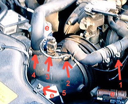
see Fig. 1 :
To gain clearance undo clip (1) & (2) and pull off connector (3).
Move this pipe to the side see (6) fig. 2. to gain more access.
Loosen the clip (4) and remove this pipe from the elbow.
Slip the two electrical connectors and the relay (e) from their clips.
Then undo the 2 bolts (5) which hold the elbow to the car.
see Fig. 2 :
Undo the clip (7) securing the bellows to the throttle housing.
Do the same for the other clip (8) securing the elbow to the air intake.
The elbow and bellows can now be removed from the car. This enables visual inspection of the throttle plate. Mine was very clean so I didn't take the throttle body from the manifold.
The throttle body can be removed by unclipping all the cables and electrical connectors and undoing the 4 bolts attaching it to the air intake (Some of these are not easy to get at, a universal joint extension helps).
The plastic elbow & the bellows can get quite messy and need a good cleaning. Carb cleaner is recommended but WARNING keep it away from the MAF on the air intake and the TPS at the base of the throttle body as you could damage these sensitive components.
Check the gap between the butterfly and the Throttle body wall to make sure its .002"
While it's out, make sure you de-coke the EGR return line where it enters the throttle body, and check to see if the EGR hoses need cleaning.
Refitting
Some people use a gasket material between the throttle body and the manifold.
Torque the bolts (14lb ft) after replacing. If you're using a "gauge" type torque wrench, best look at a longer extension..... one of the bottom is a real challenge to try to meet a torque spec with a large wrench.
Also be careful not to overtighten the clip sealing the bellows to the elbow. When I took mine off the plastic elbow here was squashed allowing lots of air in (see Fig 3). A new elbow is 30 UKP so I heated the kink with a hot air gun and used a curved wood former to push it back into place.
Calibration : As long as you don't move the TPS beneath the Throttle body, You shouldnt see any changes in base idle speed. If you're having any rough or irratic idle problems, then go through the motions of setting the TPS voltage, which is described in Haynes then do the Idle adjustment (see below)
10.6 - Adjusting Idle Speed ( ,
)
Set the throttle plate gap to .002(.05mm). This is the gap between the throttle plate and the wall. To do this right, you should remove the throttle body and clean it with some throttle body cleaner and then set the gap. The throttle body/ plate gets gummed up from the crankcase vent being before the throttle.
After setting the gap, reassemble the throttle body and all parts, clamps, wires, etc.
Warm up car,
ac off,
transmission in park,
turn key off,
Turn key on but don't start car and wait 15 seconds then disconnect connector to iscv.
The iscv is just forward of the throttle body, close to the cruse control bellows.
turn key off,
hook up iscv connector,
turn key on but don't start car...wait 15 seconds,
disconnect iscv connector, (your winding the iscv closed)
leaving the iscv connector disconnected, start the car.
turn the idle speed air bypass screw on the iscv using a 7\32 inch Allen wrench till the rpm is 550 to 600.
Hook up the iscv connector.
You're done.
If the static idle is not set correctly, the rpms will hunt around. The computer is only supposed to raise the idle from base due to a load, so if the base idle is not set right the computer doesn't know what to do, hence the hunting.
10.8 - Oil Change Tip ( ,
)
Underneath the engine near the front is a large plug that looks like an oil drain plug. This plug is dark orange in color and about 2 inches in diameter.This is the access plug for the oil pressure relief valve.
If you remove the front plug, you should replace the crush washer under it. Generally there is less than 1/2 quart of oil in this area. If you drain only from here, there will be several quarts in the back of the pan. It is impossible to completely drain the engine, and the small amount of residual oil will not affect anything but the colour of the oil after the change.
10.9 - Head Gasket ( ,
)
10.9.1 -
Head Gasket failure symptoms ( ,
)
Head Gasket Failure can come with various different symptons including :
Rough running, lack of power
White smoke
Coolant level getting lower with no obvious leaks
Water in oil
The last one often needs to be taken with a grain of salt when checking the quality of the oil by looking in the oil filler. A white emulsion can often appear especially in colder weather and does not necessarily mean your head gasket has failed.
While some cars have exceed well above 100k miles without any problems, others have not been so lucky.
10.9.2 - Head Gasket Replacement ( ,
)
Click here to open one of the pages from the Jag-Lovers photo album including a number of high resolution pictures showing the re intstallation of the head after a gasket change.
It will not replace the Manual but the pictures are really good and it will give you an idea of what's involved.
If you thought that you can't change a head gasket in your own car... this will prove you wrong !
but if you're not up to it, get it down by a pro...
|