|
6.1 - Engine Warning (early) ( ,
)
Early XJ40's had the fueling failure disabled by taping back the BLUE-GREEN wire at the instrument pack connector. The connector is a 28 way yellow one. Without this wire connected the engine management controller cannot send the codes to the instrument pack.
An erroneous error, #1, "Spurious crank signal" could be displayed on these early models. This was supposed to be raised when the starter is engaged and the engine rpm is over 2000rpm, or no crankshaft signal at all. Turned out it was coming on all the time, so the firmware was changed in the ecu to never check for this fault.
Early vehicles had the wire pulled out of the connector. No wire, no faults! The wire can be reconnected, but expect to see this incorrect fault reported.
6.10 - Electric Windows ( ,
)
The relays for the power windows are part of the switch assemblies. 1 relay for up and 1 for down in each switch. I don't think there are any relays for the mirrors, but if there are I think they would also be in the switch panel.
Pull off the door panel and check for power at the window motor and then trace back from there. Most likely cause is broken/loose wiring or connectors.
If you are getting power to the window motor, the gear assembly may be seized, but this is unusual on a drivers door. The gear assembly can be removed from the motor and coaxed back into working order with lots of penetrating oil and a suitable spanner on the cog.
6.11 - Instrument Panel Electronics ( John Ping,
October 20, 2001
)
On XJ40s, whether Model Year 1988 / 1989 or Model Year 1990 through 1994, the "Instrument Panel" is microprocessor controlled. Although it sounds technically sophisticated, it quite conventional by modern design / production standards. All signals, regardless of their original source, pass through the Instrument Panel's "electronic pack" prior to be routed to the appropriate gauge or display. All instruments within the Instrument Panel are replaceable on an as needed basis. Thankfully, the Instrument Panel has a solid reputation for being quite trouble-free (especially, the 90-94 years). All Instrument Panels were manufactured by Lucas and are considered precision devices.
The early models (pre-90 Model Year) utilize a combination of analog gauges (speedometer and tachometer) along with quasi-digital segmented display for ancillary parameter monitoring. As true to the early years, this Instrument Panel is subject to problematic quality control. The design is known to suffer from "cold solder" joints and other electrical connection concerns. Typically, the problems can be resolved with some judicious troubleshooting and re-soldering.
The Instrument Panel was revised to a more "driver friendly" conventional analog gauge layout for the 90 through 94 Model Years. The later models use 58 position stepper motors as the "four" ancillary gauges (voltage, fuel level, coolant temperature and oil pressure). As previously mentioned, the signals for these instruments are feed into the electronic pack microprocessor and then independently supplied to each Instrument Panel gauge. The speedometer and tachometer are the only true analog instruments, but again, being supplied via the electronic pack.
Note: Instrument Panels between the early model years and the later model years are NOT interchangeable. Panels can be interchanged between the associated Model Years, but the original "electronic pack" should be retained if possible to ensure the odometer reading for the vehicle is correct.
6.11.1 - Instrument Panel Removal ( ,
October 20, 2001
)
Removing the Instrument Panel is a simple task. Do not be intimidated by the electronics or the fact that you are "pulling something out of the dash" as it is truly easy. The following is a step-by-step method for removing and replacing the Instrument Panel.
Step #1 - Disconnect the negative battery cable. Always ensure that this action is performed as there are continuously hot circuits in the area of the driver's footwell and Instrument Panel.
Step #2 - Remove the driver's footwell upholstery panel. There are typically four or five No.2 Phillips head sheet metal screws and two fir-tree type push-pin type connectors holding the upholstery panel to the frame.
Step #3 - Remove the driver's footwell sheet metal panel. Again, there are typically four No. 2 Phillips head sheet metal screws securing this panel to the frame.
Step #4 - Remove the "passive restraint module" (or other electrical components) from the left side of the steering column. This action is to provide additional working clearance when removing the Instrument Panel from the dash. The passive restraint module (or other components) is typically mounted with one or two No.2 Phillips head machine screws. There is no need to electrically disconnect these devices, just drop them from their mounts and position out of the way.
Step #5 - Release the Instrument Panel two multi-pin electrical connectors on the backside. Lying on your back within the driver's footwell, locate the rear of the Instrument Panel (crčme colored plastic device approximately 15" in width). Connector "A" is the smaller of the two and is located on the right side (based on your current positioning). Squeeze the small release tabs in the center of the connector while pulling outward. The connector will release without significant effort. Connector "B" is the larger of the two and is located on the left side (based on your current positioning). Squeeze the small release tabs in the center of the connector while pulling outward. Again, the connector should release with minimal effort.
Step #6 - Remove the Instrument Panel mounting screws. The Instrument Panel is secured using four No. 2 Phillips head machine screws. Again, while lying on your back within the driver's footwell, locate the two screws on each side of the lower Instrument Panel. At the bottom front corners of the Panel, locate a single machine screw on the black frame. The second machine screw for each corner is located within the Speed Control / Trip Computer or Lighting Control Pods. An access hole to allow removal of these fasteners is provided in each Pod. Disconnecting or removing the Pod is not required. With the four fasteners removed, the Instrument Panel is ready for removal.
Step #7 - Dislodge the Instrument Panel from the dash. While lying on your back within the driver's footwell, use your hands to apply force on the rear side of the Instrument Panel attempting to push it towards the steering wheel. It will dislodge without tremendous effort as its just a simple press-fit.
Step #8 - Re-position the Steering Wheel and Remove the Instrument Panel. Release the steering wheel positioning level and pull the steering wheel outward as far as possible. It is not necessary to remove the steering wheel to facilitate Instrument Panel removal. With the Instrument Panel dislodged from the previous step, guide it outward and sideways for complete removal. The Instrument Panel should now be within your arms.
In this case, re-installation is honestly the reverse of removal. Just ensure the Instrument Panel is properly re-fit in the dash prior to installing fasteners. The Instrument Panel dash pad has locator tabs at the front corners, which mate with slots on the lower dash frame. Significant effort is not required to re-install the Instrument Panel into the dash.
6.11.2 -
Instrument Panel Electronic Pack ( John Ping,
October 20, 2001
)
The Instrument Panel "Electronic Pack" is mounted to the rear of the panel. As mentioned before, it is a crčme colored rectangular shaped plastic module with dimensions of approximately 15" length x 5" width x 2" height. Inspect the two multi-pin female type connectors located on the rear of the pack to ensure / rectify any visible defects such as deformed pins or corrosion. Always use a quality electronics parts cleaner to removed films or dust/dirt from these connectors. No petroleum-based products should be utilized! With the Instrument Panel inverted to allow access to the "microprocessor electronic pack", remove the ten (10) No. 1 Phillips self-tapping screws which are located around the perimeter and connector portion of the module.
With the cover plate removed from the module, the microprocessor board is visible. There are no "owner" repairable items on this board. The microprocessor provides output to the gauges / displays via the use of three "printed circuit board type" ribbon strips. Release each ribbon strip by pulling up on the strip locks on each end of the ribbon. With the locks released, the strip can simply be pulled upward to release. This step should be performed to the other two strips.
The electronics pack can now be disconnected from the Instrument Panel by releasing the two plastic clips at the bottom and pivoting upward on the module to approximately a 90-degree position such the hinges on top will release. Note that the hinges on the module are split to allow separation from the Instrument Panel.
Note: The electronic pack has a specific "speedometer calibration". If replacing this item, ensure the replacement electronic pack is marked with the exact "speedometer calibration" as the original electronic pack or the speedometer indication will be incorrect. The odometer reading is stored within the electronic pack. When installing a replacement pack, the odometer will not readout with the original vehicle mileage.
As with the Instrument Panel, installation is truly the reverse of removal. Ensure the three printed circuit ribbon strips are securely installed on their connectors and the locking devices are in proper position prior to re-installing the rear cover plate.this case, re-installation is honestly the reverse of removal. Just ensure the Instrument Panel is properly re-fit in the dash prior to installing fasteners. The Instrument Panel dash pad has locator tabs at the front corners, which mate with slots on the lower dash frame. Significant effort is not required to re-install the Instrument Panel into the dash.
6.11.3 - Gauge / Warning Light Pack ( John Ping,
October 20, 2001
)
A word of caution, the gauges are precision devices and are easily damaged if handled in a careless manner. Ensure that your work area is clean … including your hands. To access the Instrument Panel gauges, it is necessary to remove the Instrument Panel clear bezel. This step is accomplished by releasing the ten (five top and five bottom) plastic clips located on the gauge pack. With the ten clips removed, carefully separate the two housings.
Support the gauge pack in a manner such that the instruments are not touching any surfaces. With the gauge pack vertically supported, it is now necessary to remove the wood veneer panel. It is attached to the gauge pack with seven No. 1 Phillips head self-tapping screws. Fastener access is from the rear (printed circuit side) with two screws along the top, three screws in the middle section and two screws along the bottom. The Vehicle Condition Monitor (odometer) will release with the veneer panel. Ensure the four-pin black connector is released (pull upward) and the two odometer light bulbs are removed. Carefully separate the veneer panel from the gauge pack. Keep the gauge pack positioned vertically to ensure no instrument damage.
Remove any instrument as desired by first locating the mounting tabs for the affected instrument on the rear of the gauge pack. Press the small tabs to the right and left side of each pin to release the pin. This is precision work … be careful! Each instrument has three pins. The ancillary gauges can be replaced independently, but the speedometer / tachometer is replaced as a single module.
Install the new gauge as desired by pressing the three pins into their circuit board female receivers. Carefully position and re-install the veneer panel using the seven small self-tapping screws. Carefully position and join the clear bezel housing to the gauge pack. It is wise to clean the inside and outside of the clear bezel using a glass cleaning solution prior to re-attachment with the gauge pack.
A quick check for electrical circuit continuity can be performed using a conventional digital multi-meter. Trace out the circuit path from each instrument pin to the printed circuit ribbon strip end. Each circuit should have minimal resistance. Mount the electronic pack to the rear of the gauge pack (hinge and clip mechanism). Carefully mount the three printed circuit ribbon strips to the connectors on the electronic pack. Ensure the ribbon strips are fully seated and the connector locks are properly positioned. Mount the electronic pack rear cover plate and you are finished.
Follow the directions for re-installing the instrument pack into the dash.
Note: If the tachometer fails for no apparent reason, it its possible the inline buffer resistor (approx. 6.8k ohms) between the negative side of the ignition coil and the Instrument Panel has failed (open circuit). All models may not incorporate this design, but absolutely check the wiring schematics to determine if it applies to your vehicle. If this problem occurs on your vehicle, just bypass the original failed resistor and install a new one in the circuit to restore tachometer operation. It's a very simple matter to splice the new resistor circuit into the existing wiring harness near the ignition coil.
Note: The warning lights (tan holders) used on the Instrument Panel are the "long-life type". They will rarely need replacement as they are seldom illuminated. The illumination lights (white holders) on the Instrument Panel (center of the electronic pack) should be inspected (slight twist to the left and pull out) for deterioration (smoking / graying of the inside of the bulb). Replace any suspect bulb prior to re-assembly. The two odometer (VCM) lights at the bottom of the electronic pack (tan holders) are always illuminated and it is prudent to replace these bulbs (or swap with other low priority warning bulbs if replacements are unavailable) prior to re-assembly.
6.12 - VCM Display ( ,
)
Intermittent loss of the Vehicle Condition Monitor display.
The most common cause of this is a failure of the printed circuit solder connections to the transformer which supplies the high voltage to the fluorescent display, especially if a thump to the front top edge of the instrument momentarily brings on the display.
Remove the Instrument panel completely, take off the back, take sensible anti-static precautions remove the small circuit board at the opposite end from the monitor display and you will see the transformer. Examine the pin connections with a magnifying glass as the cracks can be difficult to see re solder and all will be OK.
6.13 - Trip Computer (early models) ( Pete Crosby,
December 4, 2001
)
Don't give that little computer and the Jag engineers too much credit with regard to range.
It seems that the range shown is based strictly upon the amount of fuel the computer thinks is in the tank (based upon the level and NOT based upon fuel usage calculated from injector "on" time) and the currently calculated average fuel economy (which IS calculated based upon miles traveled and injector "on" time). Hint: check your range after filling the car up but before you reset the computer. It will calculate the range based upon the current average MPG and the amount of fuel it decides is in the tank, as read from the level sensor.
Average speed is calculated from engine run time and distance traveled.
Fuel used is calculated from the amount of time the injectors are open (i.e. injector "on" time). This is why dirty injectors or a bad fuel
pressure regulator will cause the computer's calculation of fuel usage to be way off when compared to how much fuel it actuall takes to refill the tank.
Instant fuel economy is calculated using injector "on" time and distance traveled and is recalculated about every 5 seconds.
6.14 - Light ECU troubleshooting ( Bruce Taylor,
December 10, 2001
)
|
The following info relates to a strange intermittent electrical problem on a 1992 Daimler/VDP
When the fault is present, all of the following happen:
- The audio warning screams continuously (even with the ignition key out!).
- The bulb failure indicator is on (sure, but read on...).
- The radio works fine but the antenna won't go up (or down if it is already up).
- The direction indicators don't work (no clicking, no flashing, left or right).
- The internal and puddle lamps don't come on when you open doors.
- The internal overhead lamp doesn't come on with its switch either, but the map reading lamp works normally.
- The hazard lamps don't work.
- The keyboard illumination doesn't work.
- Everything else seems to work fine!
Sometimes after a few hours of audio screaming, the fault clears itself spontaneously and suddenly all of the above things work normally! Then for no apparent reason the screaming restarts and all the above failures are back again together.
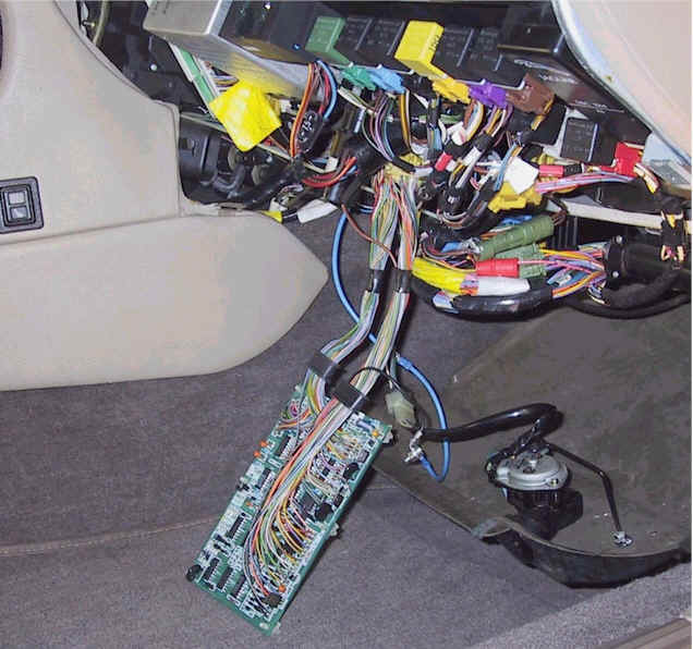
The microprocessor unit (I'll call it the ECU for short, but of course this is not the engine management ECU) is mounted on a vertical bracket at the back of the wiring area behind the passenger side knee bolster. Although the top end is inaccessible it is held by a hook, so it's only necessary to remove the lower 2 self-tapping screws to get the unit out. In addition to torx screws, the ECU cover is secured by 2 rivets with fancy heads to discourage tampering, err, inspection. The screws are quite tight but made of butter, so you may want to push the screwdriver right in to get some bite. Be very careful about this if your screwdriver has a long tip! Some of the hollow screws are just above the internal pc board and the screwdriver could damage traces on the board.
The ECU uses a National Semiconductor COP325 microcontroller. That's an industrial temperature (-40 to +85 deg C) version of the COP425, a 4-bit CMOS microcontroller with 1K ROM that cost about $1 each in the late 1980s. It's a simple, low-density, double-sided pc board with a few ICs and discrete components that would be quite repairable if a schema were available. Unfortunately the makers (AB, of BFM fame) have omitted to stick that on the inside of the top cover!
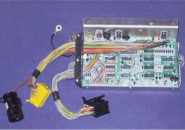
To access the solder side of the pc board, remove the screws securing the 3 TO220 components to the case and snap out the 6 plastic clips. The leads are long enough to test the open pc board in the car quite conveniently with just an extension to the ground lead as shown in this pic : fuel economy is calculated using injector "on" time and distance traveled and is recalculated about every 5 seconds.
Direction indicators are closed, the wires read about 0.1 ohm to ground at the ECU input. When the inputs are open circuit, a DVM reads about 145 mV. This is probably not a DC level and the indicated voltage may depend on the capacitive load. In my case the voltage fell to near zero when the intermittent fault was present. I don't have the proper factory schematics for my car but I found the wire colour coding of the "typical" schematics in Haynes accurate. The New Zealand M.A.P. manual was also helpful because it indicates connector pin numbers, which Haynes does not, although there appear to be some errors such as B159/B13 crossovers.
The construction quality of this ECU was rather mediocre, the 5v regulator in my unit had been soldered squint and the insulating bush just squashed up instead of entering the hole in the case. The board had been wave soldered and some joints did not look too healthy. There were quite a few solder spatters from the subsequent hand soldering of the connecting wires. Because of the solder mask they did not appear to be causing short circuits, though.
I tested the ECU after resoldering each row and it became OK after doing the row in line with the label "KCE DV-0". There is nothing special in this row (like a high thermal mass connection that can give a dry joint if it's not heated long enough). Since I didn't actually see a defective solder joint I can't be sure that was the cause of the intermittent fault. It's possible there was an internal defect in a component which was cleared by the thermal shock of the resoldering and may reappear in the future.
I wouldn't trust this box in a really critical application, but when it fails the main inconveniences are just the lack of turning indicators and the screaming audio warning, which doesn't stop one getting home.
Anyway the ECU then appeared to be running solid so I boxed it up again, using nice 4BA screws (no longer than 0.2", to keep clear of the pc board) in place of all the original fasteners. These are the ideal size (3.6 mm dia) and preserve the British heritage!
There were many different versions for different models, markets and years. My car is VIN 639732. Within the range VIN 594576 to VIN 648923, from 1990 MY onwards, 4 litre models only, the parts fiche shows that USA vehicles were fitted with DBC4968, Canada/Middle-East/Taiwan with DBC4967 and other countries (including mine) with DBC4966. The design changed again from VIN 648924.
A UK Jaguar parts supplier lists the cost of a replacement DBC4966 as GBP 740. Adding shipping and local tax, that is 25% of what we paid in November 2000 for the entire car!
6.15 - Interior Light door switch ( Dave Lockensgard,
December 21, 2001
)
The interior lights and the door open warning light are triggered by a microswitch that is part of the door latch mechanism. Different from the normal push-button arrangement at the door hinge that is usually used. The switch provides a ground signal to the cpu that turns on the lights and the warning.
The problem could be in the switch or in the wiring. To test the switch, take off the door panel and find the connector going up to the door lock. Check the two wires for continuity in the door open and door closed position. If that work O.K., trace the wiring back to the car's interior, looking for a break. Sometimes the wires near the hinge will break due to flexing. It's helpful to have a wiring diagram.
If the switch is bad, you have to remove the latch mechanism to replace it. You might invest in the Haynes manual for the car if it comes to that.
6.16 - Fuel Filler Door Release ( Jim Moore,
December 25, 2001
)
If the fuel filler door release stops working you can still use the boot lever to open and procrastinate until you are really tired of opening the boot everytime you need to fill up...
To remove the unit loosen the clamps on the filler extension, and the vent hose(at rear of filler extension). Pull off the drain hoses (1 at rubber cover, 1 at solenoid). Pull the extension out the top through the rubber.
From inside trunk, take out the 4 bolts holding the solenoid unit from the bottom. Unplug it and take it out of the car. Take out the 6 small phillips head screws on top and remove the solenoid and electrical unit from the plastic housing. Sticking out the end is a pressure switch.
Carefully remove the foam cover and lift up the plastic contact strip. You will see the 2 brass colored contacts under it. which can be covered with carbon from arcing. Clean them up (scrape with a knife blade) also clean between them.
Next clean the contact secton of the plastic strip (has a metal section in the center that contacts the brass strips when pushed down).
Before reassembling the solenoid unit, plug it into the car and test it by pushing down on the contact plastic section with you finger. Due to wear, it may take more pressure than could be asserted with the foam piece installed. You can put some silicon sealant on top of the plastic strip and set a small washer the size of the contact section into it, did not use the foam piece.
Now the plunger that is activated when pushing down on the filler cover sits on the washer and has no problem making the preasure switch activate.
Reistall everything (reverse of removal) and it should work perfectly if the inline fuse is not blowing, this is probably the problem. If the fuse is blowing it is probably the soleniod itself.
6.17 - Seat Heaters ( Alan Heartfield,
February 6, 2003
)
The seat bottom is easily removed by removing the single phillips screw in the front of the seat. Lower the seat back to at least the half way back position. The seat cushion can then be lifted up, front first. The red connector for the switch on the side of the seat cushion must be disconnected first. To disconnect these connectors, squeeze the two protrusions on the sides of the connector, and pull the plug and socket apart. The seat can now be raised to about 45 degrees, giving clear access to the motors and heater connectors.
There are two heaters in the seat. One in the cushion and one in the back. They are wired in series, so if either heater quits, neither will work.
Remove the connectors from their clips and disconnect the ones that go to the seat cushion. There will be another red one for the cushion heater, a yellow one for the back heater and a green one and a black one. The seat cushion can now be removed from the car.
Now is a good time to clean up under the seat and make sure the motors are all running freely. I put some dry graphite lubricant on the actuating rod threads.
Turn on the car ignition and the seat heater switch. Check for voltage at the red connector for the seat heater at the end that remains in the car. There should be full battery voltage here. If not, then you have found the problem.
Jumper between the two pins on the yellow connector and use a good ohmmeter to measure the resistance between the pins on the red connector for the seat heater. There should be approximately 2 ohms. If so, then the problem is with the seat back heater. This was my case, so I now had to access that heater.
First remove the small phillips screws on each side of the seat back. On the left side of the seat is a larger phillips screw holding a plastic hole plug. Remove this also. Get into the back seat of the car and pull down and back on the seat back with the map pocket in it. The whole back of the seat will come off, exposing the motor and heater wiring.
Now remove the clips so the seat front cover can be carefully peeled off towards the front of the car. I also released the two lower clips holding the diaphragm. As the seat cover comes off, you will find a couple of green bungee cords that keep the cover taut. Release the one on the left from the rail at the lower rear of the seat back.
The seat cover does not have to be entirely removed. Just loosen the frontleft side until it can be lifted up sufficiently to see the heater. Two black wires feed the heat from the bottom, centre, front of the seat back. There is a layer of cheesecloth covering the seat heater grid.
In my case, a section of the cheesecloth was charred about 3" up from the seat back bottom. I cut a slit in the cheesecloth so it could be peeled back, and found the connection between the black wire and the grid had melted. I cut away the damaged wiring on both sides of the problem area, and using crimp connectors and a short length of SXL wire, bonded them together again. A better choice would have been some teflon wire. SXL is a high temperature wire with an insulation that will not support combustion. I had some on hand, but no teflon wire. When crimping, do not use the cheap style of crimper that clamps the crimp between two arcs cut in the tool. Use a crimper that has an arc and an opposing dimple such as the Thomas and Betts tool. Otherwise, cold flow will not occur and the crimp will just get hot and you will have the same problem all over again. Alternatively, solder the connection, which is what Jaguar (Recaro) did.
Test, reassemble, and toast some buns.
|


