|
7.9 - Brake Booster conversion using XJ6 booster ( Steve Marsden,
June 20, 2005
)
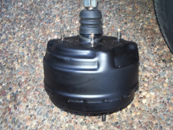
XJ6 Vacuum brake booster from donor car
xj40 Brake booster unbolted from pedal box
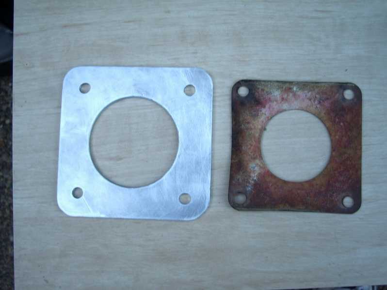
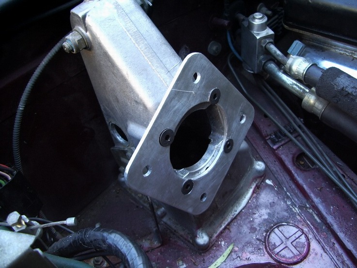
Adaptor plate fabricated using gasket as template
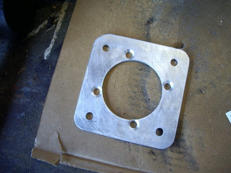
Adpator plate with pedal box holes drilled and countersunk

Pedalbox M8 studs need removing, 2 shown
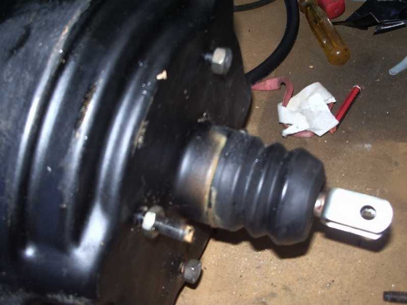
XJ6 booster studs cut down to about 10mm length, 2 shown
Adaptor plate screwed to pedal box awaiting booster
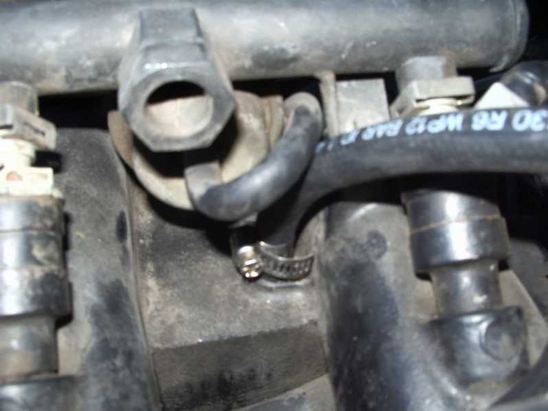
1/4" vac line attached to spare connection on intake manifold
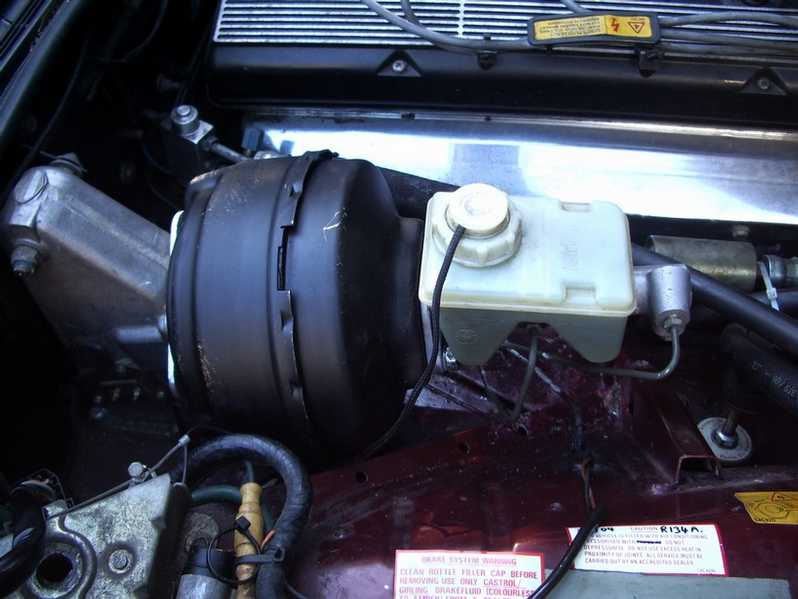
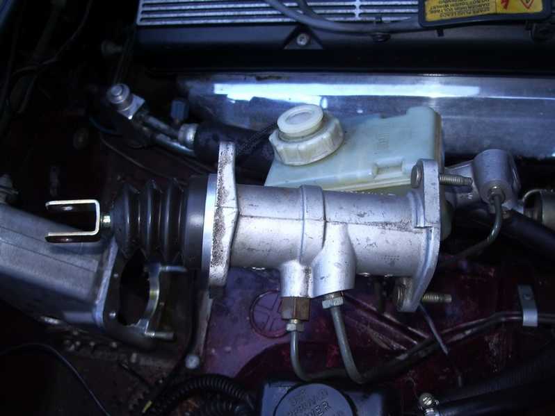
Steering fluid tank moved for access, booster in place
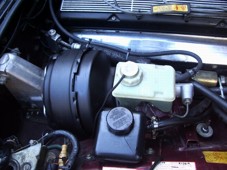
All installed and working, plenty of room for everything!
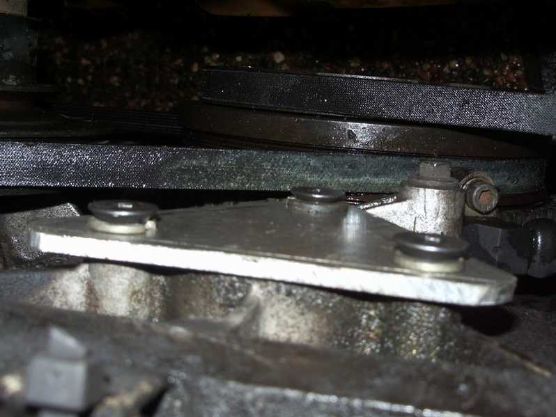
Hydraulic pump removed and cover plate fitted

Hydraulic bits removed, ebay here I come !
|
Jaguar 1987-89 XJ40 Brake booster conversion
This is a modification I made to my own 1989 Sovereign and is the result of hunting around in scrapyards, cutting and drilling 5mm sheet alluminium to fabricate 2 plates and some trial and error. I cannot say whether this modification will work on your XJ40, and I cannot accept any responsibility for anything that doesn't quite work like mine did.
This will only be suitable for 1987-89 XJ40's fitted with the Girling Hydraulic brake booster system, and with no SLS installed. I came up with this modification after noticing how similar the Girling system on an XJ6 was when compared to the XJ40 in terms of the master cylinder and its dimensions.
The Booster I used was from a 1982 Jaguar XJ6, and I believe that most XJ6 and XJS models from the 80's use a booster which is dimensionally similar and may be used without too many problems. Mine cost me AU$85 from a wreckers yard and with a cleanup and a coat of paint works great ! My car is a Right Hand Drive, and the booster fits without any bodywork modifications, there is plenty of room. I am not sure if anything is in the way on a LHD car, but if there is I suggest you move it out of the way.
Total Cost of this project :-
Pre-owned XJ6 booster $85.00
5mm alluminium plate ( offcut from local engineers merchants ) $10.00
7 x M8 Counter sunk socket head bolts 16mm long. $ 7.00
1.5m of ╝" vac/fuel hose $15.00
TOTAL COST $ 107.00
( That's for everything, nothing extra to buy !!! - maybe a bit of paint ? )
Here's how it's done:-
Testing The 'New"Booster before you start doing anything
Ě Test your XJ6 brake booster ! There's no point going ahaead if your XJ6 pre-owned booster is duff. Connect the booster to a vacuum source on the XJ40 intake manifold. Mine had a spare blanked off source just behind the fuel regulator toward the front of the engine, right on top of the manifold. It was a 3/16" tube just sitting there with a black rubber cap on it. If yours doesn't have a vac source available, you may have to make one - I guess you could drill and tap into one of the many points on the manifold that look like they are intended for the purpose. ( Just next to the aircon vac tube might be a good place ! ) Be careful not to get any metal shavings in the manifold though ! )
Ě With the engine off, it should be very hard to push the actuator into the booster. If it moves easily the booster may be no good. However, with the engine running pushing the actuator will be very easy and the piston should move in and out at the rear of the unit.
Ě When you are happy that you have a good working booster, disconnect the vac hose and give it a clean and a coat of paint to make it look fit for your jag !
Removing the old hydraulic booster
Ě With the ignition off, depress your brake pedal until the accumulator pressure has been dissipated and the pedal goes hard
Ě Remove 2 x nuts Holding Master Cylinder to Brake booster and gently slide the master cylinder out of the way being careful not to damage the brake pipework.
Ě Remove 2 screws holding the power steering fluid tank and move it out of the way to allow better access to brake booster area.
Ě Remove 2 x rubber bungs on the pedalbox to allow access to the pedal/booster fixing pin, and after removing the circlip gently knock out the pin.
( You do not need to remove the pedalbox, it's fiddly but you can get to the pin and circlip with a pair of snipe-nose pliers ).
Ě Undo the 4 nuts holding the hydraulic booster to the pedalbox, undo the 2 hydraulic lines from the booster, and remove the whole unit. The Hydraulic lines can be moved aside for removal later.
Preparing the hardware
Ě The pedalbox has 4 x M8 studs sticking out of the front of it. These can be simply unscrewed, you may need to use a strong pair of pliers or grips as they may be a bit stiff - but they do come out !
Ě Cut down the 4 studs on the front of your XJ6 booster to about 10-12mm length, remember to put nuts on first to clear the threads after you have hacksawed them off. ( they are too long when offered up to the pedalbox if not cut down ).
Ě My Booster had a gasket which I used as a template to mark out the adaptor plate which you need to fabricate yourself which fastens the booster to the pedalbox. ( You will see that the studs and holes don't line up at all ! )
Ě The adaptor plate I made was 130mm square and made from 5mm thick alluminium plate. Mark it out before you do anything else. You can make templates by placing a piece of card/paper over the booster studs and on the pedalbox holes. Make sure that the fluid reservoir on the master cylinder will be level when the booster is fitted - check it before you start drilling.
Ě When you are happy with the paper version mark up your plate and drill the holes. I used a 10mm drill for the pedalbox holes, countersunk deep enough for M8 screws, and 8mm holes for the booster studs. The big hole in the middle I cut 75mm, just because I had a cutter that size, but 60mm would be better as my hole was verging on the 'too big' side of things.
Ě Cut off the corners and round them off with a file to make it look nicer, and make sure that there are no burrs anywhere, it needs to be nice and smooth.
Ě The brake master cylinder needs to have the 2 mounting holes opened up as the studs on the XJ6 booster are slightly bigger. I used a 10mm drill.
Putting the vacuum system together
Ě Nearly Finished ! The adaptor plate can now be screwed onto the pedalbox using M8 x 16mm screws ( anything from 8-16mm length will be OK )
Ě The brake booster can then be offered up the the pedalbox adaptor plate, making sure that it's the right way up and that the master cylinder fluid tank will be level and that the Vacuum connection is on the engine side of the booster. You will find that it goes straight in, and the booster actuator should line up with the brake pedal with a bit of adjustment. Once the nuts are on, ( I only fit 3 ! ) insert the pin back through the pedal/booster connection and replace the circlip. ( I cheated here and drilled a small hole through the pin and used a split pin to secure it instead of the circlip.)
Ě Press the brake pedal and check that the pedal is quite hard to press and the the brake light works OK. Because of the 5mm plate, the brake light switch may need to be adjusted simply by slackening off the 3 fixing screws and moving it before tightening the screws again. ( This is mounted on the side of the pedalbox )
Ě Now the Master Cylinder can be offered up to the booster and secured in place with the 2 nuts and washers . It just fits right on there, easy as that !
Ě Connect the booster to the Manifold Vacuum , I used ╝" fuel hose and an adaptor to 5/8" which is what my booster connection used. I also fitted a check valve ( non -return valve ) in line which I also got from the Donor XJ6 as part of the booster. Tighten up all the hose connections and run / secure the hose away from the hot exhaust side of the engine. ( I used cable ties along the fuel rail )
Ě Replace the steering fluid tank and bolt to inner wing in original holes.
Removing the other unwanted parts
Ě Thats the install complete, but what ever you do, don't do what I did - please don't start your engine! HSMO everywhere, lots of mess to clean up, an extra hour of work that you didn't really need because the pump is still on the car!
Ě The old Hydraulic stuff has to come off. Basically it just unbolts from the car without any problems at all. The only fiddly bit is the hydraulic pump. I removed my top radiator hose so that I could get better access. I just about managed to get the 3 bolts out using a small socket wrench without having to remove the cooling fan, but it's very tight and you need patience. I then used the pump as a template to make a cover plate that bolts on where the pump came off. It's just a triangle shaped piece of 5mm alluminium with 3 x 10mm holes drilled in it. I made a paper template using the pump as a guide and drilled to fit. That area of the engine is dry, so there is no need for a gasket, just a plate to keep dust out.
Ě The other bits to come off are, HSMO tank, Valve Manifold, Accumulator assembly and all associated pipework. Disconnect the electrical connectors and make a note of which wires go where for disabling the warnings - later.
Ě Put the top hose back on and top up coolant.
Ě After a cleanup and a quick check around the engine bay for stray tools etc, start her up ! The Brake Booster should work right away. My brake pedal felt a little softer than when the hydraulic system was on there, more progressive as you push the pedal, and the brakes work really well.
Ě The low HSMO warning and Low Brake Pressure warnings will be active, so to fix this simply insert a wire link between the pins of each connector pair that connects to the HSMO level switch and Low pressure switch. The High level pressure switch connections are to be left open circuit. ( no link ) The low pressure switch is the red/yellow wire and the high pressure is black/yellow. Each is paired with a brown/pink wire so make sure you get the right one.
Good Luck Jag-Lovers.
Steve Marsden
June 2005.
1989 XJ40 Sovereign, 3.6 Auto.
|


