| ||||||||||||||||||||||||||||||||||||||
| ||||||||||||||||||||||||||||||||||||||
|
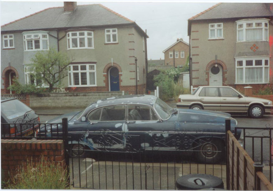
Please click pictures for larger sample Background. I bought my 420G back in 1992 for the princely sum of £400. It had been the victim of a ‘cherished number’ transfer, and so I ended up with a vehicle bearing an age related plate and a very suspect M.O.T.
When I went to view the machine, it had no brakes, the cross-ply tyres
were literally thread bear, one sill was chock-a-block full with Motorcycle
News and filler, and one of the tail pipes had dropped off!
Solution 1. A replacement 4.2 engine was purchased, condition unknown, and fitted
to the Battlecruiser. That turned out to be a bigger job than I first thought!
As the engine had come from an XJ, the exhaust manifolds and the triple
carb manifold had to be swapped – however, most of the studs seemed to
be either too short, or far too long and subsequently they had to be swapped
over as well. The stud swap took forever using the good old nut and locknut
technique. I also swapped the starter, engine mounts, water pump, alternator,
PAS pump and associated brackets and to cap it all the oil filter and pressure
regulator housing were incompatible. What a carry on!
Solution 2. Purchase V12 engine and fit into Battlecruiser. Simply fabricate engine
mountings and exhaust system, sort out wiring and plumbing, and then drive
to MOT station. I had generously allowed myself a couple of months to pull
off this minor miracle, but it was to take me the next 7 years (off and
on) to complete! This turned out to be an initial attack of 3 or
4 months graft, a break of about 5 years, and then a major attack to finish
the job.
Fitting a V12 into a 420G. A big decision, and an early decision was to retain the B.W. Model 8
gearbox, which I had just overhauled before the original XK engine blew
up, and for it to remain in its original position. Therefore the
prop shaft would not need to be altered, and the gearbox rear mount, selector
cable and filler tube / dipstick could remain in their original positions.
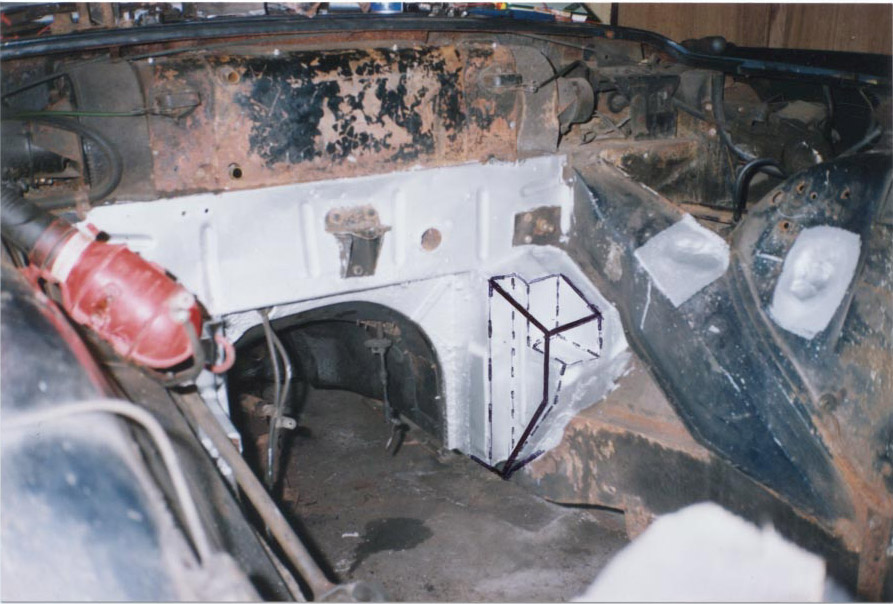
A considerable amount of work had to be done to the ‘front of transmission
tunnel’ / footwell areas to make room for the rear of the V12. The thick
black lines on Photo ‘A’ show the original profile of the footwell
on the nearside. Photo ‘B’ shows the same modification to the offside
footwell / tunnel – ultra close to the handbrake mechanism.
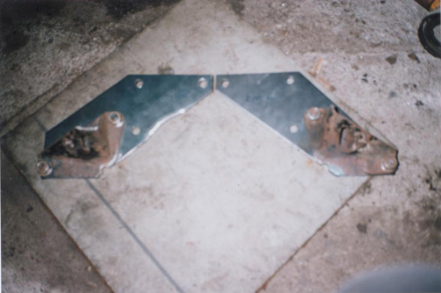
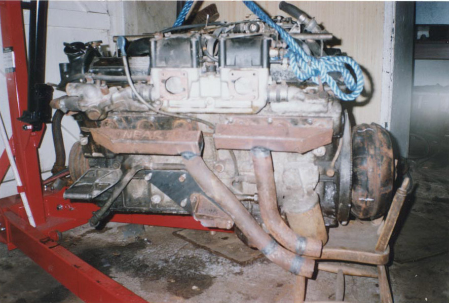
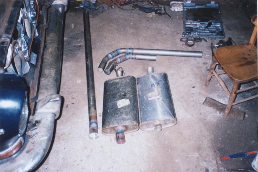
An exhausting time ! Photo ‘D’ shows the home-made exhaust manifolds and down
pipes for the nearside. The ‘design criteria’ was to get the pipes back
far enough to clear the engine mounting, whilst hugging the oil filter
dangerously close so as not to fowl on the ‘chassis rail’ running through
the engine bay. I decided to tackle this side of the engine first, to get
my confidence up, as I knew that the offside of the engine would be an
absolute nightmare.
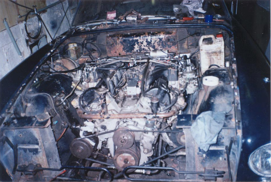
I didn’t realise at this point that if I had planned the down pipes less than a half inch further forward, they would have fowled the steering tie rod which runs across the vehicle just in front of the sump – oh – and I nearly forgot , I had to be able to get to the sump plug !! Have a close look at the offside of the engine. You might be able to see a very bright and shiny area just underneath the front of the engine mounting plate. If you haven’t already guessed, this is where I attacked the engine with an angle grinder to provide clearance for the incredibly huge steering box – remember the earlier photo ? The challenge was to remove just enough metal so that as the engine moved around, it wouldn’t constantly thump against the steering box, and to leave enough metal so that the strength of the engine wouldn’t be compromised around such an important area – very nerve racking ! A Massive Setback. After the completion of the exhaust manifolds and down pipes, and the
hammering of the nearside inner wing to make way for the carbs, I decided
that it was time for the V12 to be finally lowered into position and bolted
in, but I thought it would be a sound move to start the engine before fitting
it, as it was an unknown quantity, and I still remembered the saga of the
XK oil burner ! As the engine had stood for goodness knows how long,
the very least I could do was check, clean and re-gap the spark plugs.
The first couple of plugs came out with no trouble at all, then…..oh no…a
tight one! From previous experiences with the XK engine and the Rover V8,
the technique of just to say moving the plug, then tightening, then slackening
a few degrees more, then tightening again and repeating this procedure,
very gradually increasing a few more degrees every time had worked wonders
but not so in this case. The spark plug sheared off and left all of its
threads in the cylinder head. On removing the rest of the plugs, the same
thing happened again, but on the other cylinder head! After trying
fruitlessly to remove the sheared threads, by repeatedly heating with a
No.15 nozzle in the welding torch followed by immediate chilling with freezer
spray to break the bond then subtle use of an ‘easy out’, I decided that
it was easier to purchase a second V12 engine than mess on removing both
cylinder heads etc, etc, etc.
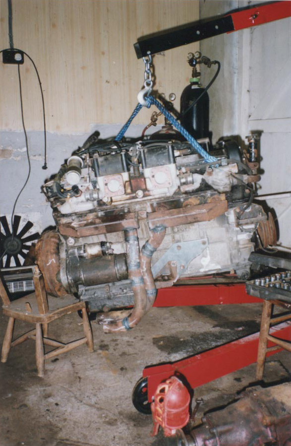
Photo F A few phone calls located a PRE-HE engine just south of Birmingham for
£150 with spark plugs removed ! When I got the engine back
home, I changed it over to carbs, attached the home made exhaust down pipes,
connected the oil cooler, poured two gallons of oil down it’s throat, and
with it not only suspended from the hook but also lashed down to the feet
of the engine crane, we prepared to start the engine.
Blast Off !! Picture the scene.….. a V12 on down pipes, lashed to an engine crane, Ray and Colin on the nearside of the engine, Chris and me on the offside. Ray’s job was to pour petrol into a big funnel to feed the four Strombergs, Colin was in charge of the choke on the nearside, I worked the choke on my side and all of the throttles, and Chris had the honour of twisting wires together to operate the ignition and starter motor. Contact ! Ray poured petrol into the funnel for what seemed like an eternity whilst the carbs filled up, then Colin and I set the chokes to full. Chris switched on the ignition and engaged the starter. The engine turned over for ages, and then began chuffing and popping out of one of its down pipes. Moments later there was a loud bang, a tube of flame shot out of one of the carbs and then the engine roared into life ! The temporary oil pressure light went out, and as I revved the engine, it seemed to levitate – straining all of the ropes. As we were all beginning to choke on exhaust fumes, it was time to let go of the controls and as the engine slowed, spluttered and stopped, I realised that I had created a monstrous hybrid – a V12 folding crane! Time to fit the engine. I quickly found that the engine would not go in with all of its down pipes on, and so was forced to remove the nearside pipes. In fact , things were so tight that it practically had to be dropped in vertically, and then waggled around the steering box, before arriving on its mountings. There was no chance of attaching the bellhousing at this point, however, with just the torque converter on, the engine was shoe-horned into position. I had previously twigged that when the engine was in position, it would be impossible to install or remove the starter motor and so just before the engine went into the hole, the thoroughly overhauled starter was loosely held in position with a few bolts and its wires were connected. Once the engine was in position, the bell housing was fitted and I could see that the rear upper engine mount had lined up perfectly as per the original plan. This was a milestone. On a job like this, with so many engineering nightmares to overcome, it was very reassuring to find things finally coming together. By now, those of you who are reading this article ‘wide eyed’ in disbelief,
will be gripped with panic as you realise that I now have to fit the incredibly
heavy cast iron Model 8 gearbox from underneath. In fact some of you will
probably scream when I report that if wasn’t going to go in! Underneath
a 420G, the vast expanse of floor pan is mind blowing. You can’t even see
the prop shaft forward of the centre bearing as it really does run in a
‘tunnel’ , totally enclosed by the floor. The gearbox fits up into the
structure of the vehicle extremely snugly, the result being that to attempt
to fit the gearbox onto the bellhousing safely and accurately, without
damaging the torque converter, requires dropping the rear of the engine
by an angle of nearly 40 degrees. Guess what?
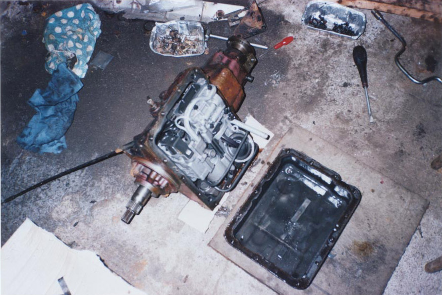
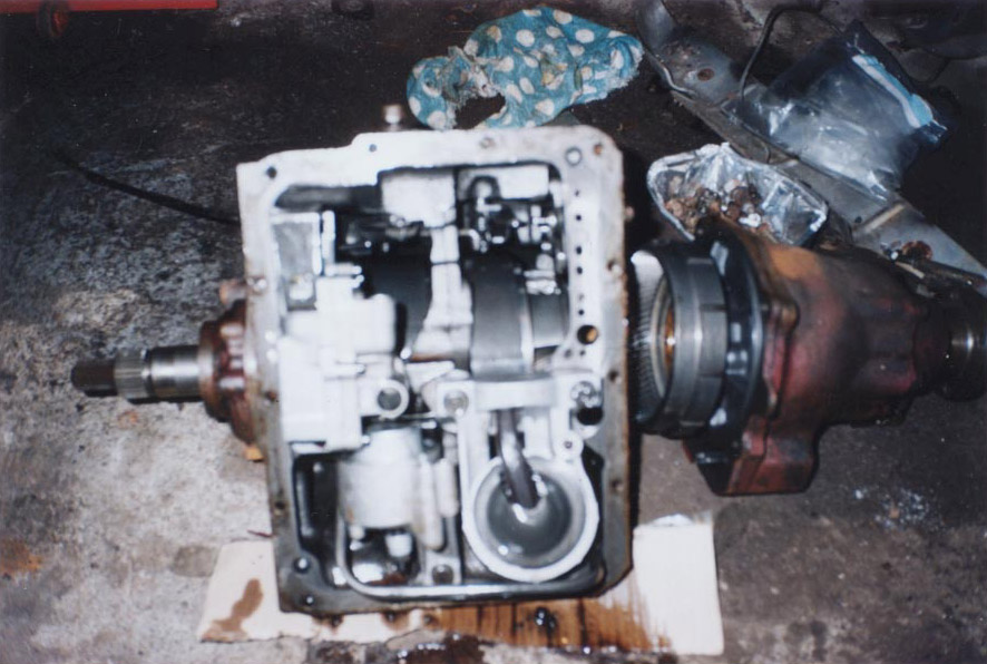
Bands, clutches, pipes and oil ! The brain wave was a master stroke of pure madness. As Edmund
Blackadder would have said ‘The plan was so cunning, you could brush your
teeth with it!’ The weight and overall length of the gearbox were the major
problems, so the plan was to take the gearbox apart and then in the tradition
of all good Haynes manuals which say that reassembly is the reversal
of removal, simply put it back together attached to the engine – laid on
my back, working upside down – a daunting prospect, but the only way out
.
Whilst working on the auto box, I had ton’s of clean newspapers to lay parts on, plenty of clean rags, and never allowed my hands to become filthy. Cleanliness is important with automatics! Taking automatic gearboxes apart can be a bit tricky, so if in doubt, go and see a professional. Once the gearbox was in position it was time to make the rest of the
exhaust system. I fabricated “Y” pieces for the down pipes once they
had reached the sump. Photo ‘I’ shows some of the exhaust
pipes coming together, only one silencer for each side, arched sections
for getting over the drive shafts and through the suspension cradle, and
one of the long bits for going down the length of the vehicle.
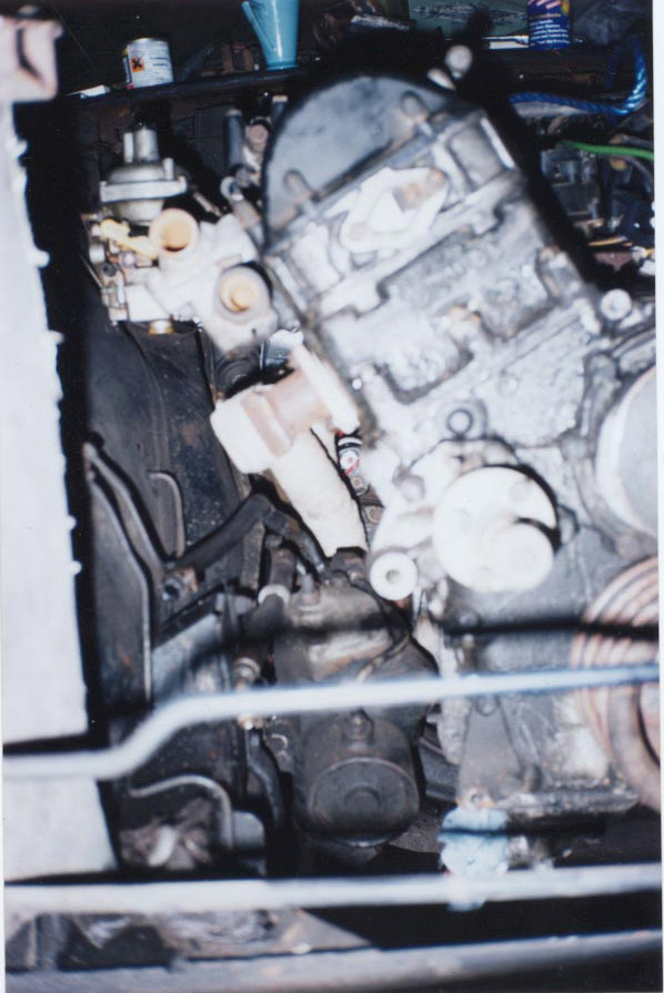
When it came to balancing the throttles, it became apparent that my air flow balancing meter would not fit between the carb mouths and the inner wings, and so a different approach would be necessary. I removed the damper assembly from all the carbs, so that the bottom of the butterflies were visible. Then I partially opened the throttles by pressing the accelerator pedal slightly and then clamping it in position with mole grips. By bending a gas welding rod into an ‘L’ shape and inserting it through the damper opening so that it located in the gap between the bottom of the butterfly and carb body, the welding rod could be used as a slip gauge to ensure that each butterfly is set to the same position, starting with the rear carbs and finishing with the front carbs. Following this procedure ensures that any errors due to worn or slack linkages and bearing play on the throttle pedestal are eliminated as there is tension in the whole system during adjustment. Photo ‘K’ shows just how tight the offside of the engine was. You can see how the down pipes follow the line of the engine to provide clearance for the steering column (just visible), the starter motor nestling at the back (now unremovable !) and you might be able to see the steering box nudging its way into the area of the engine that I ground away!
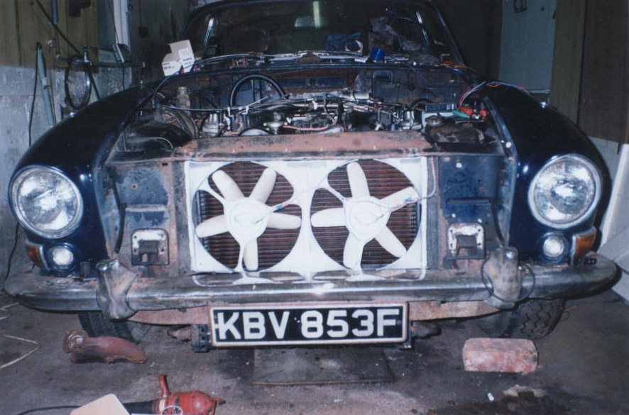
With cooling firmly on the agenda it was crisis time again. There
appeared to be no room left to fit an engine driven cooling fan.
In fact, the fit of the V12 proved to be so tight that I cannot slide my
hand in between the water pump pulley and the radiator .
The solution for each assembly was to pull the fan off the motor shaft and refit it backwards, then get the direction of rotation correct. Next time you are tucking into a nice bowl of vegetable soup, try turning your spoon upside down and see how long it takes you to finish the soup – that’s the nature of Nissan Cherry fans!
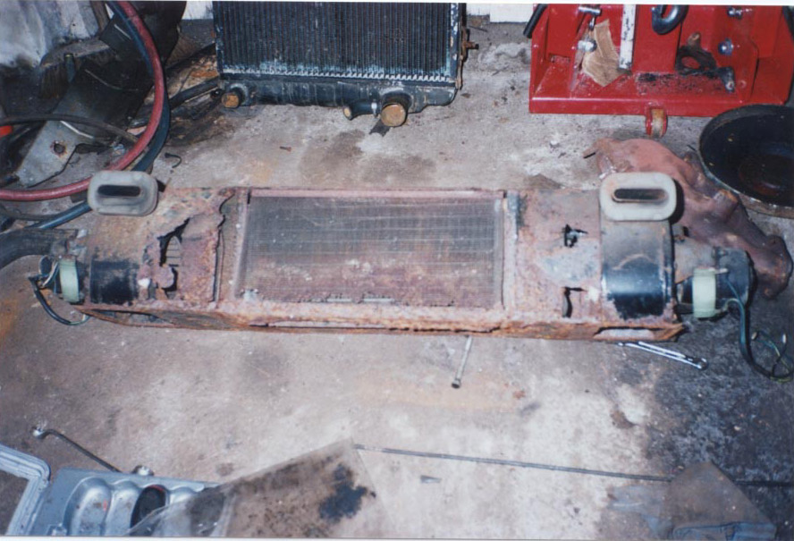
Photo ‘N’ shows the horror I saw when I removed the heater box – no wonder it was never very effective. Well, that’s my story. Needless to say there were lots more bits and pieces to sort out, that if detailed, would turn this narrative into an epic. Once the V12 job was finished a lot of money and time was lavished on the Battlecruiser to ready it for MOT e.g. front and rear sandwich mounts, radius arm bushes, caliper repairs, brake pipes, flexi pipes, front discs, various bearings and areas of welding. I am happy to report that, as of April 2000 the Battlecruiser is MOT’d and road legal. At the time of writing I have just addressed problems of petrol leaking
from the Strombergs and incorrect gear changes due to kick down cable adjustment,
and have yet to solve the relentless surging of the engine at tickover
and small throttle openings, but I’ve had a succulent taste of the combination
of V12 and 420G,and I’m addicted. It is silky smooth to drive and seems
to perform reasonably well, though on a spirited get away it seems to suffer
from a bit of petrol starvation. The petrol gauge appears to have developed
an athletic nature – I can’t remember it moving as quick as it does now
when compared to how it used to be.
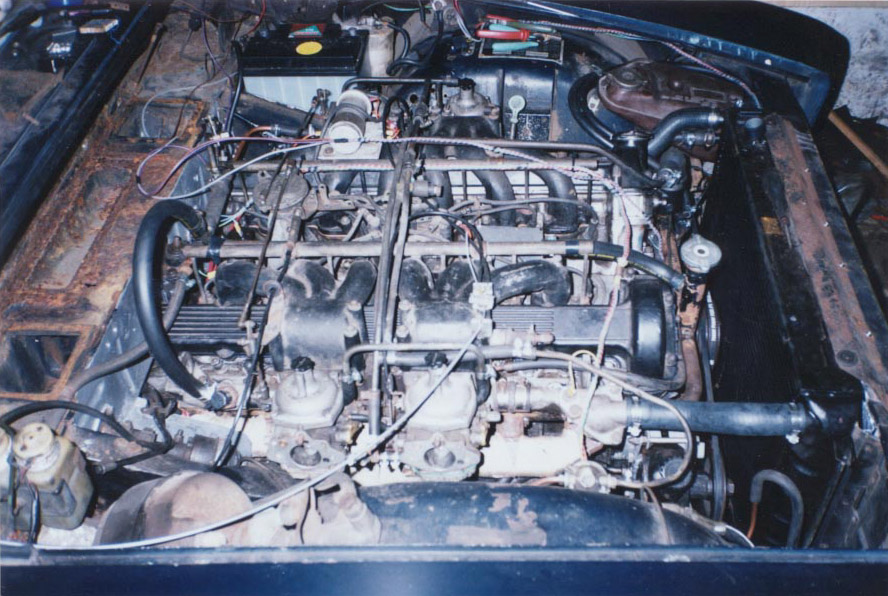
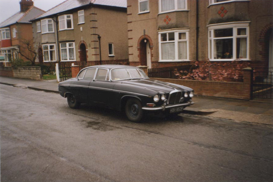
The Battlecruiser badly needs a repaint and rechrome but that will have to wait as I’m now nearly bankrupt but very happy. Photo O. The Battlecruiser lives! Does anybody know what happened to the few original V12 420G’s that Jaguar converted as a test bed for the engine ?
Last Update 06 June 2000 Back to Saloons Back to Mk10/420G |
|
| ||
 |
Improve your Jag-lovers experience with the Mozilla FireFox Browser!
©Jag-loversTM Ltd / JagWEBTM 1993 - 2024 All rights reserved. Jag-lovers is supported by JagWEBTM For Terms of Use and General Rules see our Disclaimer Use of the Jag-lovers logo or trademark name on sites other than Jag-lovers itself in a manner implying endorsement of commercial activities whatsoever is prohibited. Sections of this Web Site may publish members and visitors comments, opinion and photographs/images - Jag-lovers Ltd does not assume or have any responsibility or any liability for members comments or opinions, nor does it claim ownership or copyright of any material that belongs to the original poster including images. The word 'Jaguar' and the leaping cat device, whether used separately or in combination, are registered trademarks and are the property of Jaguar Cars, England. Some images may also be © Jaguar Cars. Mirroring or downloading of this site or the publication of material or any extracts therefrom in original or altered form from these pages onto other sites (including reproduction by any other Jaguar enthusiast sites) without express permission violates Jag-lovers Ltd copyright and is prohibited |
|