| ||||||||||||||||||||||||||||||||||||||
| ||||||||||||||||||||||||||||||||||||||
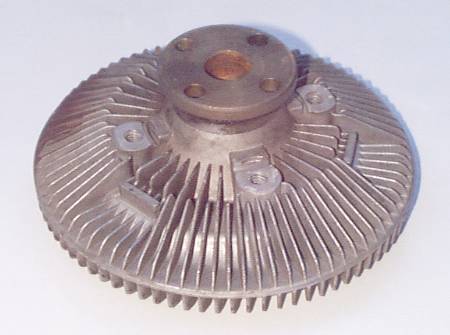
Jaguar V12Thermostatic Fan Clutch -Four-Bolt Type
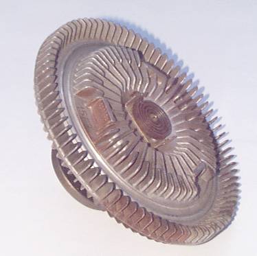
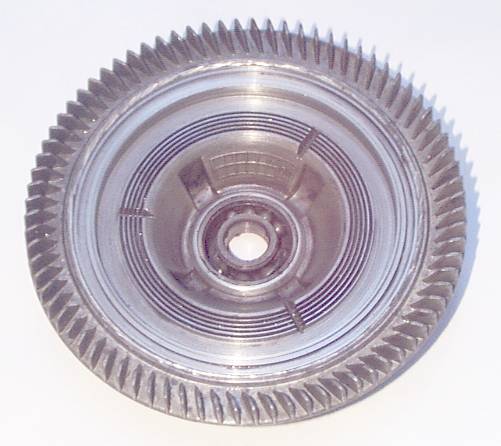
These fan clutches seem to come with a small blob of silicone sealant on the hook end of that thermostatic coil; the blob has been removed from the unit in these pictures. Purpose unknown, maybe it prevents a rattle or something. Note that the type fan clutch shown is used on most XJ-S's and XJ12's, but not all. The early XJ-S came with a different type of fan clutch that the pulley shaft went clean through and was held in place by a single bolt on the front. And reportedly the very early XJ12's, prior to the introduction of the XJ-S, had a different type clutch that mounted with four screws like this one does. See FanClutch1.html for pictures of the mid-70's 1-bolt style fan clutch. Now on to tearing this unit apart and taking pictures of the innards. There's no point in trying to rebuild it, as replacement is not all that expensive (especially if you choose a non-Jaguar substitute); the only reason to rip it open is to see how it works! On the front there is a crimped edge in the circle between the fins at the center and the fins around the outer edge. The resulting circular ridge was cut off and the front popped out. The innards were covered with viscous fluid -- a dark gray grease -- so it was all cleaned up prior to further picture-taking. The front cover itself looks like this:
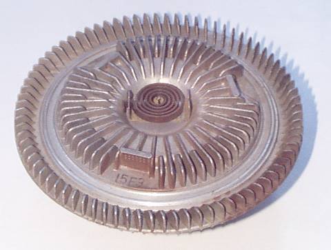
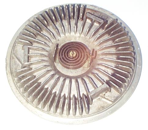
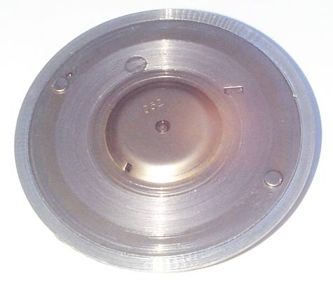
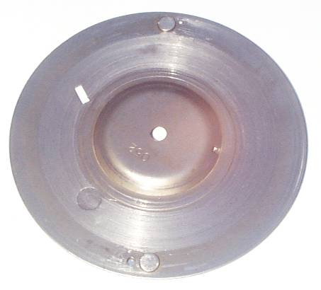
As soon as this cover was removed, the clutch unfroze. The failure of this particular clutch was that the cage inside the ball bearing came apart, chewed through the bearing dust shield, and then sent pieces of steel throughout the inside of the clutch. Some of those pieces eventually jammed between the impeller and this cover, seizing the clutch. When the cover was removed, the impeller was once again free to move. The inside surface of the cover, in the picture above, shows the circular scoring caused by the objects scraping around inside; in an operational fan clutch, this should be unblemished sheet metal. More on the cover later. Meanwhile, the clutch itself looks like this with the front cover off:
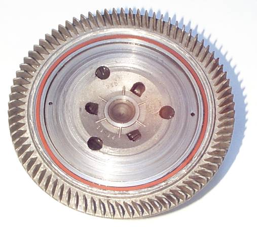
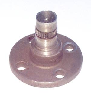
The red circle is a seal for the cover, actually a square-section sealing ring. It's very soft rubber, much softer than the typical O-ring. This one was in excellent condition -- this seal wasn't the problem here. Again, you can see lots of circular scoring around the circumference of the impeller. This is a cast part and should have an as-cast surface, since it never contacts anything but grease when the clutch is working right. Note that the end of the shaft is visible, and is deformed at the end to hold the impeller securely in place. This is a steel shaft that's deformed here, so the impeller will not be coming off easily. So, after grinding the end of the shaft to remove the deformation and hammering the thing apart, here's what the individual parts look like -- starting with the shaft:
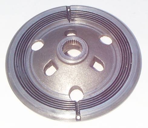
The edge of the flange is marked "EAC-4751". The impeller:
Again, that scoring shouldn't be there.
Note the two grooves leading to holes through to the other side at the outer edge. And the housing:
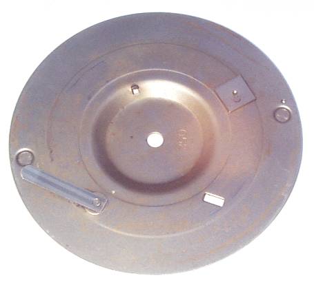
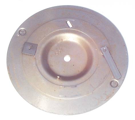
Note that the circular ribs on the impeller fit into the circular grooves on the housing. When all the spaces in between are filled with a viscous fluid, this will make a dandy fluid coupling without the need for machining fancy impeller vanes or blades. Those circular ribs are easy to machine. Also note that there are three grooves across the ribs on the housing, but only two on the impeller. Note the toasted bearing. There are remnants of the errant cage visible in this pic, and some of the balls are just rolling around loose in there. There is supposed to be a dust seal on this side, but it was a casualty of the failure. Back to the cover, which has the thermostatic goodies in it. The sheet metal cover on the back of the cover basically pops off. It looks like this:
Note that each of the two dimples at the outer edge has a hole next to it, but the holes are two different sizes; the hole at the top in this picture is smaller than the one at the bottom.
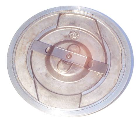
"052" is marked on both sides of this cover. It must be really important. The thing that looks like a small feeler gauge at the bottom left is another thermostatic item in addition to the coil on the outside front of the clutch. The tipoff was the striped appearance that is only apparent when the light hits it just right; this is a really good photo! Anyhow, this bimetal strip is tackwelded to a dimple on the cover (visible as a depression in the other side) and covers the larger of the two holes mentioned above. At room temperature, this bimetal strip is actually lifted away from the surface by perhaps a sixteenth of an inch, so the hole is open. When heated, the strip pulls right down against the cover and closes the hole. The square piece tack welded to the opposite side appears to be nothing more than a balance weight to counteract the weight of the bimetal strip. Now, the front cover with its own back cover removed looks like this on the inside:
That propellor-looking thing is attached to the bimetal coil on the front. As the coil is heated, the blade turns clockwise in this picture. The picture represents its location at room temperature. Now, another picture of the inside of the cover that goes over this:
The blade, as it rotates, uncovers that rectangular hole at the top in this picture. Since clockwise looking at the blade above is counterclockwise looking at this pic, the hole is covered when cold. The little tang at bottom center in this picture serves as a stop; the blade runs into it on the cold side of its travel, so it is prevented from going past the rectangular hole and opening it back up when it's really cold. You can see the scrape marks where both ends of the blade were sliding on this cover. It is of considerable importance that this cover is aligned properly when installed on the housing cover. There are no alignment tangs or dowels, however; there are only three barely-noticeable staking marks around the circumference. These marks actually show up in some of the pictures above. How does it work? Well, all I can do is guess. If we presume that the unit is not completely full of viscous fluid but is only partially full, perhaps its operation involves moving the fluid in or out of the active impeller area. The centrifugal force along with the slippage involved both serve as forces to move fluid around. The housing cover, with its own cover over it, forms a chamber that might retain some fluid away from the impeller. The small bimetal strip closes off an opening allowing fluid into this chamber when hot, and the bimetal coil on the front opens up another opening when hot to allow the fluid back into the impeller. Unfortunately, there was no clear indication just how much fluid was supposed to be inside this unit. It didn't appear to be full, but the cage from the bearing had gone the other way as well and chomped the seal, so perhaps much of the fluid had escaped. If this is really the method of operation, there is an interesting implication: how easily the fan spins when you move it by hand depends on how hot it was when the engine was shut off! If it was cool, the fluid was all in the front chamber and the fan will spin easily. If it was hot, the fluid was all in the impeller and the fan will be harder to turn -- even if it's cold now! |
|
| ||
 |
Improve your Jag-lovers experience with the Mozilla FireFox Browser!
©Jag-loversTM Ltd / JagWEBTM 1993 - 2024 All rights reserved. Jag-lovers is supported by JagWEBTM For Terms of Use and General Rules see our Disclaimer Use of the Jag-lovers logo or trademark name on sites other than Jag-lovers itself in a manner implying endorsement of commercial activities whatsoever is prohibited. Sections of this Web Site may publish members and visitors comments, opinion and photographs/images - Jag-lovers Ltd does not assume or have any responsibility or any liability for members comments or opinions, nor does it claim ownership or copyright of any material that belongs to the original poster including images. The word 'Jaguar' and the leaping cat device, whether used separately or in combination, are registered trademarks and are the property of Jaguar Cars, England. Some images may also be © Jaguar Cars. Mirroring or downloading of this site or the publication of material or any extracts therefrom in original or altered form from these pages onto other sites (including reproduction by any other Jaguar enthusiast sites) without express permission violates Jag-lovers Ltd copyright and is prohibited |
|