|
11.9 - Air Flow Meter ( John Pring & Dana Haydel,
)
|
Operation
The mass airflow sensor is a metering device designed to determine the actual ômassö of air entering the engine. It is not a volumetric flow device and it does not require external air density compensation for proper operation. The engine must receive a mass airflow signal to account for changes in air density caused by temperature and altitude. A simple volumetric flow rate signal would be insufficient.
The meter itself, is between the air filter and the inlet manifold (looks like an aluminum tube with a rectangular box on top and a cable harness connecting to it). It is considered a very reliable component typically being trouble-free, and like the engine management computer, should never be condemned without thorough investigation. It performs it primary function of metering the mass of air drawn into the engine using two thermal sensors. These sensors are located within a bypass channel in the MAF sensor. One sensor is termed the ôcompensating coilö and is unheated while the other sensor is called the ôsensing coilö and is electrically heated by the sensor circuitry. The amount of sensing coil current needed to keep the differential temperature between these two sensors constant is directly proportional to engine load (mass air flow).
The compensating coil is always at ambient temperature while the sensing coil is always attempting to create a fixed differential temperature as it is cooled by the air stream. In order to clean the sensing coil, the temperature flashes to 1000 degrees C for one second, four seconds after the ignition is switched off. The engine management computer is monitoring a voltage drop within the MAF sensor electronic circuitry, which is directly related to the current flowing through the sensing coil. This design is factory setup and calibrated. It is non-adjustable for the owner.
Early XJ40s incorporate a manual idle trim adjustment which is a 10 turn, 0-1000 ohm potentiometer built in to the air flow meter for minor idle fuel adjustment, but it works independently of the thermal sensors. Later models have adaptive idle fuel metering and no adjustment or input from the owner is necessary. These MAF internal adjustments, whether manual or automatic, are designed for emissions adjustment. The total available trim for either the manual or automatic idle fuel adjustment is only +/-10% of the nominal injector pulse duration at idle. Manual trimming is not recommended unless the owner has access to an emissions analyzer.
Functional Checks
Located on the left side of the MAF sensor is the six pin, rectangular electrical connector. This connector can be problematic. It cannot be over-emphasized that the engine management system utilizes low voltage control signals. These signals are subject to faults and high resistance joints caused by corrosion. To overcome this known problem, later models of XJ40s were equipped with gold plated connections. The connector is held in with wire clip. If you push up on the wire clip from underneath, the connector can be removed from the sensor.
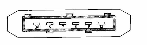
Electrical conductivity problems may be resolved by simple cleaning of the connector pins using a quality electronic component cleaner. It may be necessary to bend each male connector pins (in the MAF sensor housing) slightly to insure good connectivity. Pin layout is according to the figure below. Pin 36 is towards the front of the car. Pin identifiers may change from model to model, but the basic function remains the same.
Typical readings on certain conditions:
36 & 6 : Grounds
7 : ECU Ground
8 : Empty Connector
9 : 12 VDC Supply
12 : ECU Supply 5.0 VDC
Ignition on MAF disconnected (no start) Ignition on MAF connected (no start) MAF connected engine running @ idle (~750RPMs)
7 <1V (leakage) 7 >1V (leakage) 7 ~1.2V to 1.4V
9 Battery voltage 9 Battery voltage or slightly less 9 >Battery voltage due to alternator operating
12 ~ 5V 12 ~1.85V 12 ~1.8 to 2.5V
Diagnostics:
Battery voltages on pin 9 that deviates significantly from the chart need to be investigated further and repairs made.
Note: Should the battery be disconnected the engine management will need to re-learn the base idle. This ôre-learningö is automatically achieved by operating the engine at normal coolant temperature and driving for a distance > 50 yards. The engine may stall at idle once or twice until the adjustment values are accepted and stored within the ECU RAM.
Pin 7 readings < 1.2V can produce poor running conditions and if lower possibly no start. A voltage of <0.2V or > 4.5V is will generate a diagnostic test code (DTC 12). Refer to Fault Code List for other diagnostic help with this fault.
Pin 12 reading will typically increase towards 5V as engine revolutions are increased. This reference voltage is from the ECU.
Bench Test (Circuit Checks) for MAF Sensor:
1) Remove the electrical connector from the MAF sensor.
2) Connect a 12VDC power source (battery) to Pin 9 (+) which is normal 12 VDC supply to the MAF sensor and Pin 36 (-) which is normal ground for the MAF sensor. Ensure the power supply positive is connected to Pin 9 and the negative is connected to Pin 36. Do not reverse power supply polarity.
3) Connect a quality digital multi-meter setup to monitor voltage to Pin 7 (+) and Pin 6 (-). Ensure multi-meter positive test lead is to Pin 7 and negative test lead is to Pin 6. If multi-meter polarity is reversed, voltages will indicate negative but the absolute values will be correct.
Test 1 : Air meter stationary with no flow
Test 2 : With a blast of air in the direction of flow
Ignition
on MAF disconnected (no start) |
Ignition
on MAF connected (no start) |
MAF connected
engine running @ idle (~750RPMs) |
7 <1V
(leakage) |
7 >1V
(leakage) |
7 ~1.2V to
1.4V |
9 Battery
voltage |
9 Battery
voltage or slightly less |
9 >Battery
voltage due to alternator operating |
12 ~ 5V |
12 ~1.85V |
12 ~1.8 to
2.5V |
Diagnostics:
Battery voltages
on pin 9 that deviates significantly from the chart need to be investigated
further and repairs made.
Note: Should the
battery be disconnected the engine management will need to re-learn
the base idle. This “re-learning” is automatically achieved
by operating the engine at normal coolant temperature and driving
for a distance > 50 yards. The engine may stall at idle once or
twice until the adjustment values are accepted and stored within the
ECU RAM.
Pin 7 readings
< 1.2V can produce poor running conditions and if lower possibly
no start. A voltage of <0.2V or > 4.5V is will generate a diagnostic
test code (DTC 12). Refer to Fault Code List for other diagnostic
help with this fault.
Pin 12 reading
will typically increase towards 5V as engine revolutions are increased.
This reference voltage is from the ECU.
Bench Test
(Circuit Checks) for MAF Sensor:
1) Remove the
electrical connector from the MAF sensor.
2) Connect a 12VDC
power source (battery) to Pin 9 (+) which is normal 12 VDC supply
to the MAF sensor and Pin 36 (-) which is normal ground for the MAF
sensor. Ensure the power supply positive is connected to Pin 9 and
the negative is connected to Pin 36. Do not reverse power supply polarity.
3) Connect a quality
digital multi-meter setup to monitor voltage to Pin 7 (+) and Pin
6 (-). Ensure multi-meter positive test lead is to Pin 7 and negative
test lead is to Pin 6. If multi-meter polarity is reversed, voltages
will indicate negative but the absolute values will be correct.
Test
1 : Air meter stationary with no flow
|
Test
2 : With a blast of air in the direction of flow
|
Volt
readings |
Diagnostics |
Volt
reading |
Diagnostics |
0.4
+0.2V |
OK |
Rise
to 1.5V then returns to Test 1 |
OK |
0V |
Output
open circuit |
0V |
Output
Open circuit |
>
0.7V |
Output
Drifted Module inoperative. Sensors(s) detached |
Same
voltage as in Test 1 |
Module
inoperative |
|
|
>
5V |
Sensor(s)
wire detached
Calibration drifted |
|


