|
6.6 - Radios ( Brett Gadzinsky,
December 12, 2001
)
The 1988 to 1996? XJ40 cars had three different radios in the U.S.
- early (CB style) to 1990
- early CD version that included the woofers under the rear seat, and the later
- CD style radio that dropped the woofers under the rear seat.
The radios with the woofers under the rear seat have restrictions inside the radio that limits the audio to the door speakers to mids and highs only. The woofers get lows only.
There were a few speaker setups :
- the base model cars had 3.5 inch speakers in the doors high up
- the VDP had 4 inch speakers lower in the doors.
- the VDP also may have had the bigger 5-1/4 inch woofers under the rear seat, up from the standard 4 inch ones.
Speaker wiring is non standard. The front and back door speakers share a common (ungrounded) wire, and the system is set up so when fading to front or rear, the one speaker gets the total output power (24 watts rms).
The early (CB) style radios hold up well if kept dry, all the radios have problems getting wet from clogged drains in the climate control system.
Typical problems include solder problems on the output chips on the audio amp board (the one that has the fins), frequency display light bulbs burnt out (8 volt bulbs), missing segments on the display, buttons that don't work, and tape drive belts worn out.
The display can most times be fixed by touching up the solder at the film type connector close to the frequency display and the film connector on the main board. Sometimes the display goes bad and the liquid leaks out,or the connections to the LCD glass get rust on them from the radio getting wet.
Buttons that don't work can be the solder dots that connect things on the film on the back of the front panel, or bad button switches. Some electronics stores have the switches.
Most of these radios have adjustments on the side of the radio for the squelch and sensitivity during CB reception. Normal operation should have the radio quiet unless someone close is using a CB.
The sound of this setup can be improved quite a bit by changing out the 4 inch woofers under the rear seat to the 5-1/4 ones (DBC-10597), and changing out the very low quality door speakers to bigger and better speakers. Its possible to fit at least 4 inch speakers instead of the 3.5 inch speakers. The bigger speakers (DBC-10597) just snap in, no screws, no connector changes, look good with new grills included.
The CD style radios have problems with the frequency displays going bad, keep them dry ! They also seem to have problems blowing out parts and chips. The CD player in the trunk can be replaced by an Alpine CHM 620s, or that can be fit if you did not get one with the car. See 6.6.1 below
6.6.1 - Adding a CD Player, pre wired 1990+ ( Martin Briscoe / Christopher Pavlik,
December 3, 2001
)
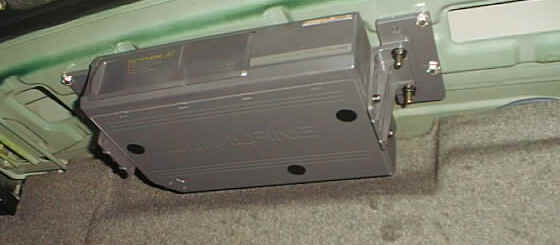
Alpine CD Changer mounted in the boot
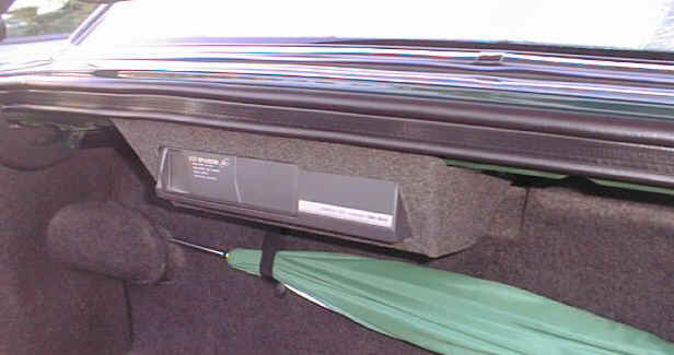
Cover some cardboard with matching material for factory look
|
Which changer to use ?
Cars which have the CD button on the radio are pre wired to take a changer in the trunk. Those without the CD button, 1986 - 1990, can use an "RF Modulated" CD Changer that plays through the radio is. 98 and up X308 must used a Jaguar supplied changer which comes with a covered panel.
Cars which have the (MS Bus) 8 pin DIN lead can accept the Alpine CHMS 620 without any problems, it is a direct plug-in and works well most listers have gone for this (Alpine apparently make the Changer supplied by Jaguar). The Alpine changer can be purchased from electronic stores for well under $ 300.
Probably most other Alpines with this plug will work too as Jos Raven reports that an Alpine 5960 & a 5952 worked in his '92 xj40 and his '95 x300 without an adapter
Cars that do not have the MS Bus require an adaptor, when in doubt look for the lead in the trunk and check to see if it is the 8 pin DIN. The cable has been found in a number of places :
1. In the forward right corner of the trunk, behind the trim panel.
2. Behind the front trim on the left hand side.
3. Coiled up behind the arial.
4. Behind the spare wheel
If your car didn't come whith the 8 pin conenctor, an ALPIL adapter is needed to get the Alpine CHM-S620 to work.
Jos reported that he needed the 4913 adaptor for connecting the 5962 & 5952 Alpines to the Alpine TDM-7531R Radio. This type has the 8-pin Din socket but has 2 separate RCA audio inputs as well which is is where the adaptor comes in.The CD style radios have problems with the frequency displays going bad, keep them dry ! They also seem to have problems blowing out parts and chips. The CD player in the trunk can be replaced by an Alpine CHM 620s, or that can be fit if you did not get one with the car. See 6.6.1 below
Mounting
The brackets that come with the Alpine don't match with the mounting holes provided in the underside of the trunk lip above the battery (factory units mount there).
Options include:
1. Mount vertically (with the cartridge door facing up) on the 'shelf' at the right side of the trunk.
2. Mount directly above the battery, this would keep it somewhat protected from being banged about by luggage or doused with rain when the trunk is opened
3. Mount on one of the shelves using velcro - advantages: quick to do & makes the changer easy to remove when parked in high risk areas, my car has the tool box under the lid so no room at the top. disadvantages: more likely to get knocked, doesnt look so good.
4. and probably the best: - Top of trunk. advantages - solid fixing, rain wont get on it, unlikely to be bumped. disadvantages:- more work, people with tool kits here wont have room.
4a. Jos shows in the picture opposite that the 'Top of trunk' fixing need not be ruled out by the presence of a toolbox, as the changer can be mounted below this.
Mounting at the top of the trunk (by Christopher Pavlik)
I put all of the mounting hardware (including "L" brackets and plastic mounting plates) together attached it to the changer. I then removed the felt like insulation from under the boot lid. to do this, I removed the spare tire (which needed to come out anyway so I could drill the pilot holes).
Holding the Changer up in the position that I wanted it in, I used a fine point magic marker (A Sharpie) to mark where I wanted the holes. At this point I inserted my finger between the panels to make sure where I was going to drill would not come through the exterior panels on the car or interfere with anything else. All was good, so I drilled pilot holes for the sheet metal mounting screws. As I was mounting the plastic mounting plates, I noticed the one side partially covered one of the holes with a beveled edge. this would have caused the plastic mounting plate to sit on an angle when I screwed it down, so I marked the plastic plate with a magic marker.
I then used a grinder to shave some plastic off the edge on the mounting plate (enough so it fit flush against the metal. Next, I screwed the plastic mounting plates on and put the insulation back up (after cutting holes so the mounting crews would go through). mounted the "L" brackets attached to the CD changer next. Plugged in the DIN Connector put back the tire and all the rest of the "junk" I keep in the boot normally.
After thinking about it, I could have gotten a piece of 1/4 inch lexan or some other plastic, and mounted the Alpine hardware to this and then used the factory mounting holes on the lexan. I am happy with the way it turned out though and it looks very professionally done.
6.6.2 - Troubleshooting ( ,
)
The LCD display only showing partial characters
Where the LCD panel connects inside the front panel there is a row of soldered connectors. Reflow all these solder joints.
Channels cutting out intermittently
I touched up all the solder joints on the power amp portion of the radio -- that's the circuit board on the top side of the radio, just inside the metal case.
6.6.4 - Electric Antenna Mast ( all models ) ( Gregory Wells, Coventry West,
)
It is possible to replace the antenna mast on 1988 and later Jaguar sedans, so long as the mast is the only problem (it is not unknown for the motors to go bad). And the replacement can usually be accomplished from outside the car with nothing more than a wrench.
The antenna mast is held into the antenna motor assembly by a ferrule nut at the base of the mast on top of the rear fender. Undo this nut and then have someone turn the radio on. As the antenna or cord is pushed up, simply continue to pull and it will come out. While the mast or cord is being ejected, note which direction the cord's teeth point.
Compare the length of the cord from the old mast to the length of the cord on the new mast. They should be very close in length. If the old mast is much shorter, there is the possibility that a length of cord has broken off and is still in the antenna assembly. If this is the case, the assembly has to be dismantled to remove the piece of cord, as the reel only has enough space for one antenna's length of cord.
With the radio still on and the antenna motor still in the extended position, insert the tip on the new mast's cord as far as possible into the hole, making certain to point the teeth in the same direction as the old mast's cord. Have someone turn the radio off and if you have the new mast's cord inserted far enough into the antenna, it will begin to be reeled in. Don't worry if the antenna doesn't go all the way down in one cycle. Just tighten the ferrule nut to retain the new mast and cycle the radio on and off a couple of more times and the antenna should seat properly when off.
6.6.5 - Security Code ( ,
)
The CD radios have a security code needed after power is removed from the radio. You may be able to get the code from the dealers if you have whatever info they need...vin or radio serial number. There is also a way around not having the code.... the code was supposed to be on a paper sticker under the hood.
6.6.6 - Adding an FM CD Changer, 1988-1990 cars ( John Ping,
February 1, 2002
)
A few words on the RF Changers ...
these are certainly not second-rate or poor quality changers. The new units ( I choose a Sony model.) are micro-processor controlled. The sound quality is excellent as the frequency response is 20 to 20k hertz and its very clean. There is no radio static as you utilize a open FM frequency in your locale. Its not a perfect setup, like a factory unit, but its an excellent compromise. The price for a quality unit is around $200. Crutchfield.com has about the best selection, price and service that I've seen.
If you think this is a reasonable option for you (after reading the installation procedure below), take your time a pick a good model. It should be able to play conventional CDs, CDRs and CD-RWs. It should be capable of vertical mounting and have a "built-in" FM modulator. Make sure the model has output adjustments for matching the CD Changer and radio sound levels. Last, but definitely not least, make sure the model has at least ten or more pre-set frequency inputs. This is really helpful if you have a lot of FM stations in your area ... I was able to find two open frequency slots.
Installation Procedure
Mounting the CD Changer:
1) The trunk of an XJ40 is the prime location. In fact, it will mount nicely slightly above the shelf on the power antenna side of the trunk. For this type of mount, the Changer is positioned vertically (make sure the adjustments on the Changer correspond to vertical mounting). Contemporary Changers are not case grounded so you do not need to find a metal mounting point. Actually, the molded carpeting is rigid enough for this purpose as Changers are light weights. You can even say that it acts as a "pre-suspension" to the precision suspension system contained within the Changer.
2) Install the mounting brackets which came with the unit to the Changer. Position the Changer about an inch or so above the shelf and mark the location of the mounting holes on the carpet with a ink marker. Set the Changer aside and, while using an awl with a sharp point, create the number of necessary mounting holes in the carpet.
3) Remove the carpet installation screw and pull back the carpet sufficiently to provide working area for your hands. Using the provided sheet metal screws attach the Changer to the carpet. This is a weak mount, but it will hold the Changer until you can install speed nuts (sheet metal nuts) on the back side of the carpet. Fit the necessary number of speed nuts and tighten the screws securely. To protect components behind the carpet from the sharp edge of the sheet metal screws (and your hands during any future maintenance), cut the necessary number of pieces from 1/8" clear tubing and slip them over the screw ends.
4) Re-position the carpet with the Changer installed and the Changer mounting is complete.
Powering the CD Changer:
1) The trunk is an excellent location for getting the necessary power supply for the Changer. All Changers typically need two 12 VDC supplies. The first power supply needs to be "hot" at all times. This is because the Changers have a memory when off and draw very low current to maintain this feature. Don't worry about battery drain ... its in the milli-amp or lower range. The second power supply needs to be activated with the ignition "ON". This is the supply that provides power to the Changer when you turn it on. Lastly, you need a circuit ground ... lots of quality grounding points in the trunk area.
2) The power supplies for the Changer will originate from the opposite side of the trunk. You could provide your supplies from the power antenna relays behind the Changer, but there is more room on the opposite side of the trunk to make the connections and add the requisite power relay. As before, remove the carpet mounting screw from the fuel tank filler side of the trunk. Best to remove the tail light assembly cover to provide more access. You need more room in this area than was necessary for mounting the Changer.
3) Locate the "auxiliary relay mount (electrical socket)" which is positioned slightly above and to the left of the Anti-Lock Brake System ECU. At least on a 90 XJ6, the ABS ECU is the device you will see in front of you. The relatively large black plastic device (on each side of the trunk) is a HVAC component designed as a ventilation exhauster (check valve). If there is no relay (for some other purpose) inserted into the socket, the power connections will be very easy. If a relay exists, you will need to splice into the wiring.
4) Assuming no relay was found in the auxiliary relay mount, use a simple voltmeter to probe the socket and determine the "continuously hot" 12 VDC lead. If you have a relay handy as a reference, it would be Pin #30. Regardless, using the voltmeter will find it.
5) Next, turn the ignition switch to the ON position and probe the socket to locate the "ignition hot" 12 VDC lead. It should be Pin #86. Note that both power supplies will be slightly higher voltage (13.5 to 14.0 volts) with the engine running. Turn the engine off after locating the voltage point.
6) After locating the two power supplies, its necessary to fabricate a couple of power supply leads. Install a 1/4" male spade type solderless connector to the end of an approximately 3' length of 18 gauge multi-strand copper wire and insert it into the "continuously hot" female connection on the relay socket. Be careful not to "short" the continuously hot lead. Likewise, install another 1/4" male spade type solderless connector to the end of an approximately 3' length of 18 gauge multi-strand copper wire and insert it into the "ignition hot" female conne joints. The resultant connection will be super strong ... and who hasn't pulled on a wire before in an attempt to remove it? It takes a bit longer to complete the wiring, but the finished product is far better than you will get at any automotive electronics shop. Secondly, use insulators (heat shrinkable tubing or pre-form insulators) on these connections. It will protect the connection from unwanted electrical contact plus its a sign of true professional installation. Lastly, ensure the wires are "bundled" together as a cable when routing using tie-wraps or black electrical tape.
7) Now that you have the power supply leads in hand, its necessary to mount an interposing relay to feed the CD Changer when the ignition is turned "ON". Based on the expected current draw of the Changer (approximately 1 amp), the use of an interposing relay is not absolutely necessary, but its always a good idea to get power loads off the ignition switch. Since its very easy to fabricate, its best to install this device. Use a typical 12 VDC automotive type cube relay ... one with a built-in tab for mounting is great. Slightly in front of the ventilation exhauster, there is an open area that lends itself well for installing this relay. There is a metal tab with a 1/4" hole at the base of the shelf (in front of the exhauster) that works great for mounting the relay. Mount the relay to the tab in the inverted position (pins up).
NOTE: Another very nice professional touch is to install a relay coil diode "reverse biased" across the relay coil input (# 86) and output (# 85). Its not absolutely required but all other relays in your Jaguar have this feature to mitigate control system voltage spikes. You may even be able to purchase a relay with this feature.
8) Using the continuous hot lead, install a fuse (to serve as master circuit protection) inline with the conductor. Don't use a fuse rated higher than 5 amp or less than 3 amp. Any type of inline fuse is okay. Solder the splice and insulate.
9) Using the ignition hot lead, install a fuse (to serve as sub-circuit protection) inline with the conductor. Don't use a fuse rated higher than 3 amp or less than 2 amp. Any type of inline fuse is okay. Solder the splice and insulate.
10) On the continuous hot lead downstream of the inline fuse, splice in another conductor (about 10' length of 18 gauge). This conductor will feed continuous 12 VDC to the Changer. Solder the splice and insulate.
11) Install a 1/4" female spade type solderless connector to the end of the continuous hot lead down stream of the previous splice. Solder the connection and insulate. Insert on to Pin # 30 (power input point) of the previously installed relay.
12) Install a 1/4" female spade type solderless connector to the end of the ignition hot lead down stream of the inline fuse. Solder the connection and insulate. Insert on to Pin # 86 (control power input point) of the previously installed relay.
NOTE: For Steps 11 and 12, cut the conductors to length before installing the female spade type connectors. Neatly bundle these two leads and position this cable behind the ABS ECU.
13) Install a 1/4" female spade type solderless connector to a 10' length of 18 gauge wire. Solder the connection and insulate. This lead is the relay output to the CD Changer. Insert on Pin # 87 (power output point) of the previously installed relay.
14) Install a 1/4" female spade type solderless connector to a 3' length of 18 gauge wire. Solder the connection and insulate. This lead will serve as the relay control power output (ground). Insert on Pin # 85 (control power output point) of the previously installed relay.
15) A quality chassis ground is located slightly to the left of the black ventilation exhauster. Cut the relay ground lead (Step 14) to length and install a solderless type 1/4" ring lug to the lead. Solder the connection and insulate (though insulation isn't actually required for this ground).
16) Carefully arrange all wiring to ensure a professional installation.
17) Bundle the two power outputs (continuous hot and ignition hot) so they can be routed across the trunk to the CD Changer.
18) Re-install the molded carpet (don't forget the mounting screw and tail light cover plate from Step 2).
19) Remove the spare tire and rear bulkhead carpet ... no screws on this carpet.
20) With the carpet removed, note that the fuel tank is directly in front of you. Also note that electrical cables are routed at the base of the tank ... this will be the same route used to provide the power supplies to the Changer. Route the two conductors securely to the opposite side of the trunk.
21) Fabricate a ground lead for the Changer using a 5' length of 18 gauge. Install a large (3/8") ring lug to the lead. Solder the connection and insulate (though insulation isn't actually required for this ground). Using one of the three spare tire jack mounting points, securely fasten the ground lead.
22) Bundle the two power leads and ground lead to the far right side of the fuel tank. Ensure you have several extra feet of conductor length so that proper connections to the power harness supplied with the Changer can be made. Do not make the power connections to the Changer at this time.
23) If you want to route signal and control cables for the Changer at this time, leave the rear bulkhead carpet off. Otherwise, go ahead and re-install the carpet.
Routing CD Changer Control and Signal Cables:
NOTE: The control cable for these types of Changers is typically a round 8 conductor type ... about 3/16" in diameter. The signal cable is really a modified small FM antenna cable ... about 1/8" in diameter. Both cables are very long (18' to 20') since you must route them from the trunk to the back of the radio (antenna) and front of the console (controller). Definitely bundle these cables together as you route them.
1) Start the process by removing the rear seat and back rest. Its an amazingly simple task ... remove the two screws (one on each side) at the front of the seat and pull the seat forward to remove it. Likewise the rear back rest is easy. Just remove the four mounting screws (two on each side) and lift up on the bottom of the cushion to dislodge the upper clips. Remove both the seat and back rest from the car to provide working access. Haynes has a good description on this task.
2) From inside the car, facing rearward, remove the upper left sound deadening material clip (near the seat belt reel). It unscrews using the flat tip of a screwdriver to start it, then your fingers.
3) Carefully peel back the black sound deadening material and you will uncover a small rectangular access port (approximately 1.5" x 3"). It is sealed and riveted to the rear bulkhead. This bulkhead cover will be the cable egress.
4) Drill out the two 1/8" rivets on the top and bottom of the plate (with a 1/8" drill). Wedge a flat screwdriver between the cover and bulkhead and free the cover from the pliable sealant.
5) With a 3' length section of rigid wire (fish tape), connect a 6' length piece of strong string to the end of the wire. Insert the wire through the bulkhead port angling towards the left side of the fuel tank. Have a helper pull the wire into the trunk area when it becomes visible.
6) Using the ends of the control and signal cables which connect to the Changer, attach the string to the cable ends. Carefully pull the cables through the bulkhead port and around the tank into the trunk area using the attached string. Route these cables to the Changer and attach them to their respective ports on the Changer.
NOTE: At this point, power has not be connected to the Changer so there is no concern for shorting the signal or control cables.
7) Position the control and signal cables behind the molded carpet at the Changer so that they are out-of-sight. Pull about 6" of extra cable so that there is no binding or tension on them. Bundle and secure as necessary.
8) From within the rear seat area, tape the twin cables where they go through the bulkhead port for protection from possible chaffing on the metal. Using duct tape or something similar, tape over the bulkhead port opening with the installed cables installed.
9) Route the control and signal cables along with the existing electrical cable down to the base of the seating area. The existing electrical cable will enter a body channel and continue forward. At the point where this cable enters the channel, branch off with the control and signal cables.
10) Continue routing the control and signal cables to the left front edge of the rear seat. Carefully peel back the carpet and position the cables underneath for protection. Leave the twin cables on the floor board area.
11) Carefully re-position the black sound deadening material and re-attach the mounting clip (Step 3). Ensure all sound deadening material and carpet is properly re-positioned. Install the back rest onto the four upper clips (Step 1) and press down (its easier with a helper). Re-attach the four lower mounting screws. Install the seat bottom under the back rest bottom (its easier with a helper) and re-attach the two lower mounting screws. Don't forget the seat belts when installing the seats.
12) Pull up the rear foot area carpet and sound deadening material. Route the twin cables toward the drive shaft tunnel (between the tunnel and the passenger seat (for LHD cars). Carefully tuck the cables under the sound deadening material and carpet stopping just in front of the passenger seat.
Installing the Control Unit and Antenna Relay Box:
NOTE: Remove the negative battery cable at this point! Further work involves tight access around sensitive electronic components. Do not take a chance on shorting some components ... remove battery power.
1) Remove the passenger side (for LHD cars) electronic and relay rack cover and remove the metal shield. Lots of push pins and screws involved but they are all accessible. Haynes can help here.
2) Remove the passenger footwell ventilation duct by pulling it back from the Climate Control Housing and wiggling it forward. This step is necessary to provide an access hole for the signal cable antenna relay box.
3) Remove the two center console screws securing the cigarette lighter and ash tray. Pull out the component and disconnect the electrical connector from the wiring harness.
4) Carefully pry up the gear shift outer bezel. Carefully pry off the gear shift cover. Pull up the handbrake and place the gear selector in Drive.
5) Working from the ash tray area, remove the two nylon wing nuts from the base of the "ski slope". Carefully lift the ski slope and free it from the upper mounts.
NOTE: Haynes has good detail on Steps 3 through 5 ... nonetheless, its a bit of a pain if the previous owner has messed up the original component locating / securing tabs.
6) Remove the six Climate Control and Radio panel mounting screws (easily accessible). Carefully pull outward on the panel and remove it. You will need to wiggle it at the top and at the gear shifter to clear the unit.
7) Disconnect the Climate Control panel cable on the right side and lay the entire assembly to the left side (drivers side).
8) Disconnect the radio antenna from its "Motorola" type connector on the back of the radio.
9) From the passenger footwell, route the antenna signal cable through the opening provided in Step 2. Depending upon the actual size of the relay box, it could be a tight squeeze. Plug the existing antenna cable into the relay box. Plug the relay box output into the radio antenna input. Position the relay box to the far left side of the Climate Control / Radio cavity to ensure it does not interfere during re-installation of the panel.
10) Reconnect the Climate Control cable removed in Step 7 and re-install the Climate Control / Radio panel. When the panel is nearly in place, there will be some minor resistance from the flexing of the cables. Lightly tighten the six screws during re-installation and then make a final pass to secure them.
11) Carefully re-attach the ski slope starting at the upper mounts and pivoting the unit in place. Re-attach the two lower nylon wing nuts removed in Step 5.
NOTE: There should be some locating washers above the nylon mount and the bottom of the ski slope for the wing nuts. These washers locate the fork mounts for the ash tray. If they were not originally there, just use four or five small 1/4" flat washers on each mount.
12) Ensure no electrical connections are interfering with the installation of the ash tray or binding on the ski slope. Re-attach the cigarette lighter electrical connector and carefully place the ash tray assembly in the cavity. Re-install the two rear ash tray mounting screws.
13) Carefully re-attach the gear shift cover. Carefully re-attach the gear shift outer bezel. Release the handbrake and place the gear selector in Park.
14) Any excess signal cable should be coiled and hidden behind (or underneath) the center tunnel upholstery.
15) Route the control cable and head unit to a convenient location on the center console. Its a personal choice, but I mounted mine slightly above the Climate Control Panel on the surround upholstery using double sided tape provided with the Changer.
16) Any excess control cable should be coiled and hidden behind (or underneath) the center tunnel upholstery.
17) Re-attach the passenger footwell ventilation duct by initially slipping the duct over the Climate Control output duct and wiggling the footwell ventilation duct into place. It mounts with a slip fit clip on the rear and a tab on the right side.
18) Re-install the electronic and relay rack metal shield.
19) Re-install the passenger footwell upholstery panel.
20) Re-connect the negative battery cable.
Final Power Up Sequence for the CD Changer:
1) From the trunk area, install the power wiring harness provided with the Changer. Route this cable along with the control and signal cable up and behind the molded carpeting to get it out-of-sight. Using about a 1' section of 3/8" split cable protector is a nice professional touch as it securely bundles all cables and adds a finished touch.
2) Connect the continuous hot lead with the its appropriate input to the Changer. Solder and insulate this connection. Ensure the inline fuse provided with the Changer for this power source is also installed in the circuit.
3) Connect the ignition hot lead with the its appropriate input to the Changer. Solder and insulate this connection. Ensure the inline fuse provided with the Changer for this power source is also installed in the circuit.
4) Connect the ground lead with its appropriate input to the Changer. Solder and insulate as usual.
5) Bundle and re-position these conductors behind the molded carpet at the base of the fuel tank.
6) Re-install the rear bulkhead carpet and spare tire.
Done!!!!
NOTE: Be sure to carefully read the operating instructions for your CD Changer before you use it. Lots of features built into a small package.
6.6.7 - XJ40 Speaker Replacement ( John Ping,
July 7, 2002
)
This article will cover the replacement of door and rear foot well speakers. The audio system used in the XJ40 line is reasonably competent. Its certainly not top-of-the-line by contemporary standards, but it can account for itself quite well when in good operating condition and teamed with a CD Changer in the boot (either a standard Changer or a RF Modulated type). The head unit is generally quite reliable, but the speakers are marginal in their performance.
At some point in time, an owner will choose to replace the OEM speakers in an effort to enhance audio performance or simply because one or more of the original speakers have failed. The actual speaker replacement work is very straightforward and can certainly be accomplished by the average owner. The actual door inner panels are slightly different on base versus Vanden Plas models, but not to a degree causing significant difficulty. This article is written based on a base XJ40 model.
Replacement of Front and Rear Door Speakers
Required Tools:
#2 Phillips Screwdriver (magnetic tip is useful)
9 mm Nut Driver
8” or 10” Flat Tip Screwdriver
Small awl or other sharp pointed instrument
Soldering Iron w/solder or 8 to 10 small wire butt splices
8 to 10 small machine screws -- #8 x ľ” or equivalent 8 to 10 small machine screw nuts & flat washers to match
Thread locking compound “Loctite” (optional)
6” wooden dowel of ˝” diameter to be used as a drift
Small mallet or hammer
1) Whenever you are attempting to a remove door panel to gain access to the speaker, or any other electrical component, absolutely disconnect the negative battery cable. Battery power is supplied to each door window motor and it’s always prudent to de-energize these circuits before you attempt any panel work.
2) XJ40 door inner panels (front or rear) are comprised of an upper and lower section, which interface to provide complete inner door coverage. Neither panel is difficult to remove nor are any specialized tools required.
3) Remove the Upper Inner Door Panels as follows:
It’s a good idea to store all the removed parts and screws in the adjacent foot well for safekeeping and easy access when you are putting everything back together.
a) Using a small awl (or equivalent), remove the small “square” plastic cover for the inner door lock release mechanism (upper right side when facing inner side of door). It pivots towards the front of the car.
b) Using the #2 Phillips screwdriver, remove the inner door lock release mechanism plastic / chrome escutcheon. It’s held in place by a single machine screw. Pull out on the door lock release mechanism and the escutcheon is easily removed.
c) Using both hands, pull out on the wood veneer panel at the inner door lock release mechanism to provide clearance and slide the panel towards the front of the car. The panel is secured on the left side by slip-in clips and they release easily.
d) Using the #2 Phillips screwdriver, remove the two sheet metal screws on the left side. For the front doors only, lift the bottom of the rubber ventilation boot at the front edge of the door and remove the sheet metal screw. Additionally, for the front door only, use the large flat screwdriver as a lever to ease out the single “fir tree” type press-fit connector. Neither of the rear doors contains these two additional fasteners.
e) Using both hands, lift the upper inner door panel until it releases from the metal ridge along the window line. It doesn’t take much effort to remove the upper panel as it slides off vertically. Store it on the seats for safekeeping.
4) Remove the Lower Inner Door Panels as follows:
a) Using the #2 Phillips screwdriver, remove the sheet metal screw located at the upper edge of the lower panel.
b) Using a ˝”small wooden dowel or equivalent drift, place it under the lower edge of the door handle screw access cover. Lightly tap each end of the access cover using the dowel and mallet in an upward direction to release the access cover. These covers can be tight if they have never been removed in the past, but they will release.
c) Using the #2 Phillips screwdriver, remove the sheet metal screw located in the middle of the door handle.
d) Using a small awl or equivalent, remove the bottom door light lens by releasing it from its locator at the rear and sliding it outwards from the door.
e) Using the #2 Phillips screwdriver, remove the lower panel securing sheet metal screw located in the middle of the bottom door light assembly. All sheet metal screw fasteners for the lower panel are now removed.
f) Using both hands (and the large flat screwdriver, if needed), carefully pull off the lower inner door panel by release the series of fir-tree type press-fit connectors along the sides and lower perimeter. Once the panel is removed, it can be laid horizontally on the seat as there is sufficient length of wire bundle to allow this movement. It is not necessary to disconnect the wiring harness, but if desired, the connectors can be released so that the panel can be moved to another more worker friendly location.
5) Remove Door Mounted Speaker as follows:
a) Disconnect the speaker positive and negative conductors by releasing the electrical connector.
b) Using the 9mm Nutdriver, remove the speed clip nut from each of the four (4) speaker fastener studs. Press the nutdriver down firmly to engage the speed nut … do NOT cut away any foam material as it is not necessary.
c) Using the #2 Phillips screwdriver, remove the sheet metal screw immediately to the left (driver side) or right (passenger side) of the speaker as viewed from the back side of the door lower inner panel.
d) Using the #2 Phillips screwdriver, remove the sheet metal screw immediately above the speaker. It is located just below the upper sheet metal screw securing tab on the lower panel … the screw was previously removed in Step 4a.
e) Using the #2 Phillips screwdriver, remove the sheet metal screw immediately to the lower right (driver side) or lower left (passenger side) of the speaker as viewed from the back side of the door lower inner panel.
f) Using the #2 Phillips screwdriver, remove the sheet metal screw immediately to the lower far right (driver side) or lower far left (passenger side) of the speaker as viewed from the back side of the door lower inner panel.
g) Steps 5c, d, e and f will release the speaker / window lift pushbutton panel from the lower door inner panel. Removal of the sheet metal screws will allow the speaker panel to be pulled away from the lower panel by 3” to 4” to facilitate access for speaker removal.
h) With the speaker / window lift pushbutton panel eased back for working clearance, grasp the speaker with one hand while pressing the four (4) speaker studs downward through the foam supporting material. After the studs are clear from the foam material, the speaker can be removed from the panel.
6) Install New Door Mounted Speaker as follows:
Typically, base XJ40 models use 3.5” door speakers while the VDPs will use 4” door speakers. Though I believe it is possible to mount either type in either model.
a) Using the wiring supplied with the new speakers and insulated solderless butt splices, transfer the old speaker wiring electrical connector to the new speaker. Another alternate method is to simply solder the old speaker wires with connector to the new speaker terminals. This is a superior method for electrical continuity and strength of joint … although it does require some soldering skills.
b) Install the new 3.5” speaker by easing back the speaker panel and sliding in the new speaker. Normally, the 3.5” models will mount with only two fasteners.
c) Using two of the small machine screws with flat washers, place these fasteners through the speaker mounting lugs and press them up through the existing holes in the foam supporting material. Secure the screws with flat washers and matching nuts from the back side of the inner door panel. The use of thread locking compound (Loctite) is a nice touch to prevent loosening due to vibration.
d) Re-install the sheet metal screws removed in Steps 5c, d, e and f. This will re-mount the speaker panel. Don’t forget to re-connect the speaker wire connector at the door panel.
7) Re-installation of the inner door lower and upper panels is literally a reverse of the removal procedure. No hidden tricks.
8) Perform Steps 3 through 6 for the other doors and the job is complete.
9) Remove Rear Footwell Mounted Speaker as follows:
This sequence is good for both 4” and 5.25” footwell mounted woofers.
a) Using a small flat screwdriver as a lever, carefully ease off the grill.
b) Using a #2 Phillips screwdriver, remove the four (4) sheet metal mounting screws.
c) Ease out the old speaker and release the electrical connector for the speaker wires.
d) Transfer the old speaker wires and electrical connector to the new speaker using solderless butt splices or by soldering the old leads to the new speaker terminals.
e) Re-connect the speaker wires to the harness by joining the electrical connector.
f) Mount the new speaker and re-attach the necessary sheet metal screws.
g) Press the speaker grill into place.
h) Repeat Steps 9a though 9g for the other footwell speaker.
|


