| ||||||||||||||||||||||||||||||||||||||
| ||||||||||||||||||||||||||||||||||||||
Jaguar XJ-S V12Digital P EFIFuel Injector Harness Rebuilding
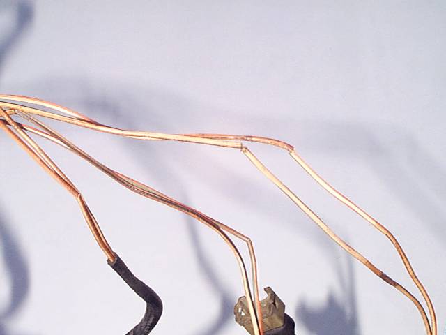
I know, you don't believe it, no automaker could do anything quite that stupid. Here's a picture of Kirby Palm's harness after some of the wrapping was removed.
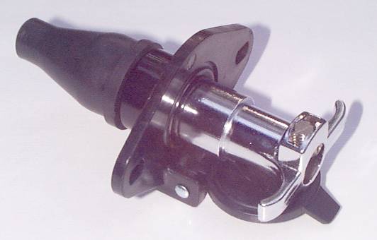
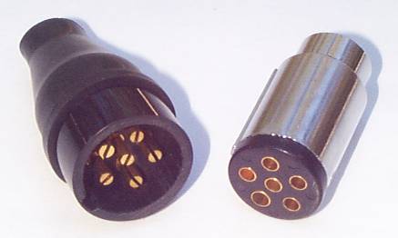
The wife says it looks like a really skinny set of snow crab legs! Here's what happens: The insulation cooks and becomes as brittle as a cracker. Then it breaks in a couple of places. From then on, any flexing or vibration bends the wires right at the crack rather than distributing the bend over the length of the wire. That stranded copper can't take that forever, and eventually the strands break at that point, and you'll be down to 11 cylinders, or maybe 9 -- some wires serve three injectors. For some time before that happens, the injectors involved will probably work a little weaker than the others, as some of the copper strands break while others continue to carry some current. The only reason this isn't a major problem with Jaguars is that there is very little flexing or vibration in this harness. Still, the cracks in the insulation allow the bare copper underneath to corrode, and eventually it will just fall to pieces. There are serious concerns, though. Rue Palmer narrowly escaped a huge underhood fire when one of these wires shorted to ground and applied 12V continuously to an entire bank of injectors. This caused the wires to glow red hot, melted all the insulation off, and melted an injector open so it was spraying fuel all over -- but nothing ignited. There is no way to know how many others weren't so lucky, since it would be impossible to diagnose this failure mode after such a fire. Palm's harness, above, was still working fine! There are several possible solutions. The first one that many owners decide upon is to run right down to their trusty Jaguar dealer and order a brand new injector harness. There are two problems with this plan: First, the new harness will still be made with PVC-insulated wire! And second, judging from the price Jaguar demands for this harness, the conductors must be made of solid gold; for the cost of the OEM harness, you could probably hire an electrical engineer to hand make you a replacement harness from aircraft-quality components. If your harness isn't in too bad a shape yet, you can do it a world of good by relocating it off the surface of the engine within that vee. A very popular fix is to relocate the harness up to the fuel rail and strap it down with some zip wraps. The fuel inside the rail is cool -- even when the engine is hot -- so it helps to keep the wires cool. Some people may not appreciate the appearance of the harness right up on top of the engine, though. There is another place to move it, and that is to lift it about an inch and attach the harness clamps under the nuts holding the intake manifolds instead of under the bolt heads holding the valley cover on. The intake manifold also runs cool, having cool air flowing through it. It's difficult to even notice that this relocation has been made without really leaning over and looking closely, yet it makes a world of difference. Not only are the wires no longer in contact with the hot block, it also gets the fabric-covered harness out of all the oil and goo at the bottom of the vee. If your harness already looks like Palm's, the best thing to do is to make a new harness. First and foremost, you're gonna need to find some suitable wire -- and that doesn't mean the "primary wire" sold in auto parts stores, because that stuff has the same PVC insulation as the OEM wire! You need wire that will withstand both the temperatures and the exposure to engine fluids that it is likely to see in this application. One possible source is Del City, which offers a "cross-linked polyethylene" insulated wire that is rated to 177ºC (350ºF). Another option is Teflon-insulated wire, which is available from Rubadue Wire Company. Obviously, any of these products are going to be more expensive than primary wire, but this is one job that isn't worth doing if you're not gonna do it right. Palm was fortunate in that Dave Johnson sent him a bunch of Teflon-insulated wire as a gift, but it'd be impolite to suggest he provide enough for everybody! He recommends buying Teflon-insulated wire from Newark at 1-800-4NEWARK. You'd like the correct colors, of course -- but you're not likely to find them. Ideally, you want about 10 feet each of OW, OU, OG, and OS, and about 40 feet of KB, all in 16 gauge. Since you're more likely to find solid colors than striped, ask for 10 feet each of white, blue, green, and gray. For the 40 feet of power wire, I suppose you could ask if they have pink. If they don't, perhaps red. Black is probably not a good idea, since black normally indicates a ground on British cars and this wire will most definitely not be a ground. Maybe brown, since brown indicates a power wire on British cars and this is a power wire. You might ask the same source about sheathing. Sheathing is basically cosmetic; it's not really needed, the car will run just fine without it, but it does keep your wires bundled neatly so they don't get tangled. The OEM sheathing is fabric, and it is falling apart -- apparently more the victim of the motor oil collecting in the vee than of the heat. Clearly, if you wish to sheath this harness at all, you'd prefer something that can withstand the heat and chemicals -- and the place selling you the high-temp wire is as good a place to ask as any. Again, Palm was lucky that Dave Johnson threw some sheathing in the gift package, too. Interesting stuff; sort of a woven black plastic that works like a Chinese finger trap -- you push it shorter and it gets fatter, but left alone will maximize its length and minimize its diameter so it clamps down snugly onto a bundle of wires. It feels like snakeskin. And despite aggressive use of a cigarette lighter to shrink down some heat-shrink tubing onto it, it suffered no damage. Johnson: "Sleeving is really neat stuff. SPC Technologies. Again it is available from Newark The stuff is amazing! The quoted spec for melting temp is 230 degrees Celsius! I have personally tested it to 250 degrees Celsius and other than it going slightly limp it escaped unharmed and once cool went happily back to being pliable." The injector connectors themselves are available brand new. However, there are two things to note: First off, most of the auto parts places sell a "harness repair kit" which includes the assembled plug with pigtail wires hanging out of it. This is really intended for replacing one bad plug on an existing harness, not building a whole new harness -- you'd rather not have all those wire splices. The second problem is the cost; auto parts shops often want eight bucks for one of those connectors, and sometimes as much as twenty-five bucks! Keep looking; the connectors are also available as individual parts: housing, contacts, boot, and the rectangular spring that provides snappage. This allows you to crimp-and-solder the wires directly to the contacts and then snap them into the housing for a professional job. And, as separate parts, all the stuff needed should cost less than five bucks per connector. The biggest parts problem is the big plug where the injector harness connects to the main harness at the right front corner of the engine compartment. This plug is apparently not available new anywhere. That leaves you with the possibility of reusing the old one, or using a different type of connector entirely and dyking the old one off the main harness and splicing on a new one. Actually, reusing the old connector is a workable plan. Since the connector and the first foot or so of the wiring are not that close to the engine, it is usually still in good shape. The only problems with reusing it are that it requires a bunch of wire splices, and that Jaguar OEM connectors have been known to develop broken connections internally and it'd be a shame to rebuild the harness and then have the connector go bad six months later. If you do decide to go with a new connector, the next problem is finding a suitable connector. The OEM connector has 8 conductors, so you need a new connector with at least that many, right? Wrong. In fact, four of the pins in the OEM connector are all connected to the same place. These can all be connected together to a single pin, so you can get by with a connector with 5 pins. The next problem is that most multi-pin connectors available come with six inches of wire -- so you still have to splice wires, which is just what you hoped to avoid when you decided to go with new connectors. What you'd really like is a connector where the wires are connected directly to the pins themselves. Radio Shack and other electronics places sell Molex connectors that fit this description, but the pins are only rated at 2 amps which might be a little light for this application. There is such a thing as a heavy-duty Molex connector, but Radio Shack only carries it in 2-pin versions. One possible solution would be to purchase the 12-pin Molex connectors from Radio Shack and use two pins for each of the four injector group wires and the remaining four pins for the power to all 12 injectors. That will provide enough current-carrying capacity, even though it may look a little hokey. Palm found another solution in trailer connectors. Trailer connectors are available everywhere, including auto parts stores, marine stores, Wal-Mart, you name it. There seem to be a couple of fairly standard types, one of which has 4 pins and the other has 6. There is a package called a "Connector Kit" number TC43780 that contains both the socket and plug plus some wire, some splice connectors, and a bracket and screws for about twelve bucks. Here is a photo of the socket and plug together:
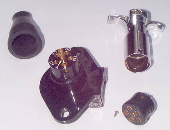
Here is a pic of the same parts all taken apart:
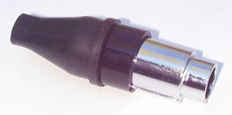
As you can see, these connectors have a really neat method of connecting the wires: they are inserted into a machined brass sleeve and a brass setscrew is tightened down on them. The back side of the connector at the lower right in the pic looks just like the back side of the other connector clearly visible. If you prefer, the same basic style trailer connector kit is available at some auto parts stores with both the plug and the socket made of chrome-plated die cast metal, rather than just the plug as in this kit. Of course, all that stuff is really bulky. So, Palm whipped his trusty hacksaw out and cut big chunks off both connectors. The finished connectors look like this:
The mounting flange has been sawn off the socket, which took the spring-loaded door with it. The T-handle has been sawn off the plug casing. Both tasks took perhaps two minutes total with a hacksaw. This surgery removes a latching feature that holds the connectors together, but that's no big deal since you're not towing a trailer with it. It also removes a wire retention feature in the metal plug casing, but that's not a big deal either; the socket didn't have one to begin with. You could, in fact, go even smaller here. You could toss the metal casing for the plug altogether if you want, and just apply some heat-shrink tubing after connecting the wires -- or find a suitable rubber boot like the socket has. The metal casing has a key down the side that fits into a notch in the socket for alignment, but there is also one pin that's larger than the other four in the outer circle of pins that also controls alignment. And you could carefully cut the outer casing off of the socket, leaving the six pins exposed until the plug is attached. The results of Palm's first-ever harness work:
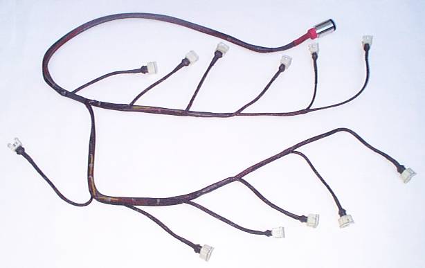
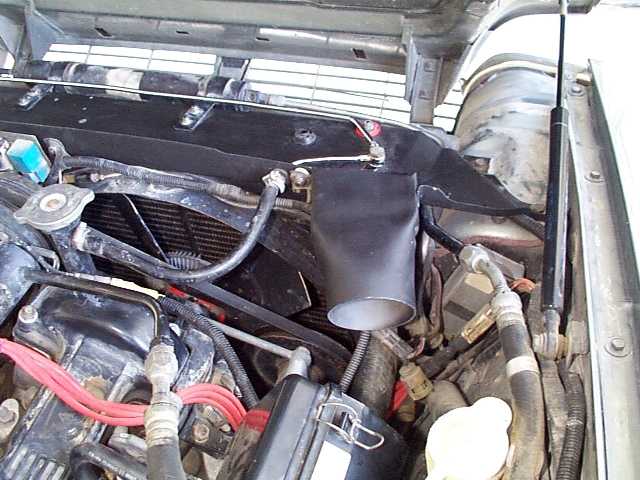
Not bad! And the best part is, it should look pretty much unchanged 20 years down the road. And here's what that truncated trailer plug looks like installed:
By comparison, here's what the OEM plug and harness looked like prior to the replacement:
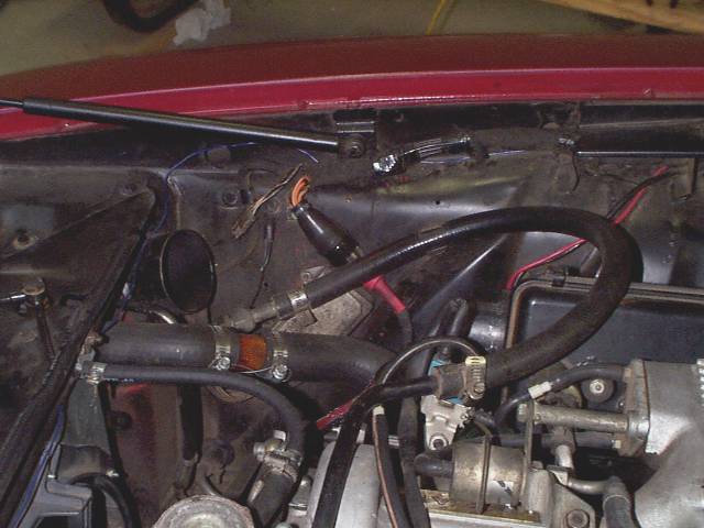
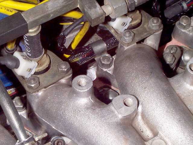
Another option, by the way, would be to go with the 4-pin trailer connectors (or any other 4-pin connector; marine stores carry a couple of types) and simply use two sets of connectors. In fact, if you go this route, you might consider making two separate harnesses, one for the left bank and one for the right. Of course, no sooner does Palm complete this job than Mark Stoner tells him where to find some really nice connectors. They are called Delphi-Packard automotive connectors, they are commonly used in modern GM cars, and they are completely sealed so they won't corrode. You can take a look at the brochure info or the catalog listings at Delphi. There are 1, 2, 3, 4, 6, and 22-pin versions; the 6-pin should work great here, or two 4-pins if you prefer. Stoner says you can get these connectors from Pep Boys or from Del City. A couple of notes: First, Palm's harness was designed from the outset to be installed at the level of the intake manifold nuts, so the 12 individual branches are a couple of inches shorter than they were on the OEM harness. They don't have to reach all the way from the bottom of the vee. Here's a picture of one of the harness clamps under an intake manifold nut:
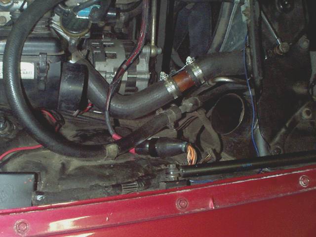
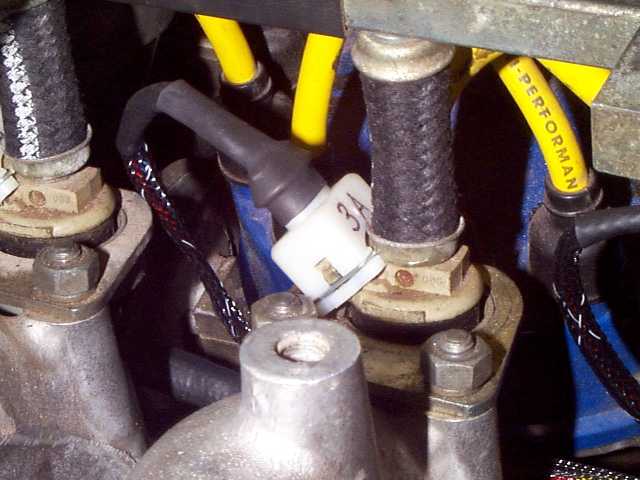
As you can see, it still takes some peering to see the harness, unlike one strapped to the fuel rail. On the OEM harness, the crossover from the A side to the B side happens forward of the 1A and 1B injectors, which means the harness passes under the A/C compressor. Palm didn't like that, as it means you have to unbolt the compressor to get the harness in and out -- the injector connectors won't fit under the compressor in place (actually, you could pop all the connectors off, leaving just the contacts on the end of the wires, but it'd probably be easier to move the compressor!). Also, Palm was interested in maximizing what little airflow passes through the vee, which means he didn't want to obstruct the tight space under the compressor with a harness. So, the crossover was relocated to behind the compressor and under the cruise control actuator, where there is plenty of room for it. That is the reason that the 1A branch occurs upstream of the crossover point, and why the 1B branch goes forward from the crossover. Also, Palm has rearranged his injectors so that all 12 connectors point towards the rear of the car. There's no good reason for this, it's just cuteness. But the individual injector branches on the harness were located accordingly. Palm didn't buy the rubber boots for the injector connectors. Instead, he bought a few feet of 1/2" black heat-shrink tubing with a 3:1 shrink ratio. This stuff will barely fit over the back end of the injector connector where the boot originally went, but it will fit; you can actually stretch it a little if need be. Once on, a cigarette lighter shrinks it all the way down onto the harness sheathing. Palm actually had another piece of 1/4 heat-shrink tubing on the sheathing already, so it's two layers thick at this point. Plus there are sections of 1/8" heat-shrink tubing on the wires where they are crimped and soldered to the individual contacts, so there are actually four pieces of heat-shrink tubing used at each connector. Here's what one looks like up close installed in the car:
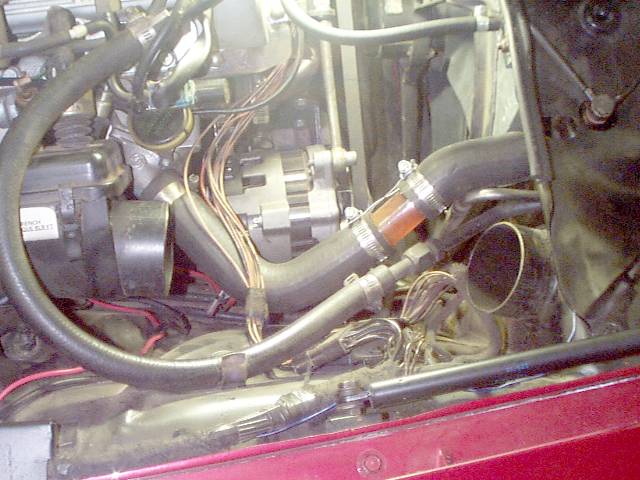
In the OEM harness, each of the eight wires coming from the main harness plug is spliced to three wires within the injector harness, and these three wires then run off to three injector connectors. In Palm's version, each of those eight wires went all the way to injector connector 6A, 5A, 6B, or 5B and the other connectors were spliced off of those. It doesn't really make any difference, just a different way of doing things. There are other ways of doing the job, of course. Here's a picture of Tom Bennett's engine compartment:
|
|
| ||
 |
Improve your Jag-lovers experience with the Mozilla FireFox Browser!
©Jag-loversTM Ltd / JagWEBTM 1993 - 2024 All rights reserved. Jag-lovers is supported by JagWEBTM For Terms of Use and General Rules see our Disclaimer Use of the Jag-lovers logo or trademark name on sites other than Jag-lovers itself in a manner implying endorsement of commercial activities whatsoever is prohibited. Sections of this Web Site may publish members and visitors comments, opinion and photographs/images - Jag-lovers Ltd does not assume or have any responsibility or any liability for members comments or opinions, nor does it claim ownership or copyright of any material that belongs to the original poster including images. The word 'Jaguar' and the leaping cat device, whether used separately or in combination, are registered trademarks and are the property of Jaguar Cars, England. Some images may also be © Jaguar Cars. Mirroring or downloading of this site or the publication of material or any extracts therefrom in original or altered form from these pages onto other sites (including reproduction by any other Jaguar enthusiast sites) without express permission violates Jag-lovers Ltd copyright and is prohibited |
|